
Specifications


Applications Ver. 0002 AP - 31
AP.4.3 ANALOG OUTPUTS FOR THE "DIAL"
Two internal variables of the Drive can be represented permanently on the machine's operator
panel by means of volt-meters.
The most often monitored variables are:
On spindle drives: Power in use, TV50.
On axis drives: Motor torque, TV2.
on both: TV3, portion of available power being developed by the motor.
This variable is given in a
0
/
00
and is valid for synchronous and
asynchronous motors in any duty cycle.
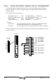
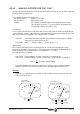
1st example:
Let us suppose that we have a volt-meter with a measuring range of +5Vdc corresponding to
a range from 0% to 100%. We wish to use it to represent the percentage of power being used
with respect to the one available. The setting must be as follows:
OP2=TV3 Percentage of power used with respect to the maximum power available,
channel 2, pins 8/9 of connector X7.
OP4=2000 2000
o
/oo / 10volts = 1000
o
/oo / 5volts (TV3 in
o
/oo)
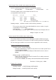
2nd example:
We installed a volt-meter with a measuring range of +12Vdc corresponding to a range
between 0% and 200%. We wish to use it to represent the percentage of rated power (S1)
being developed. The spindle motor has a rated power S1 = 11 kW.
The setting must be as follows:
OP1=TV50 Power feedback, channel 1, pins 10/11 of connector X7.
OP3=1833 1833 DecaWatts / 10volts (TV50 comes in DecaWatts) according to:
Even if the needle never reaches the top of the scale because the maximum output
voltage will be 10V. At its maximum power in S6 (16kW) the dial will show 8.72 V.
Warning:
If the values assigned to OP3 and OP4 are too small the electrical signal will saturate
when reaching 10 Volts.
11kW 2
10
12
18.33kW 1833DecaWatts⋅⋅ = =
+5 Volt
32
0
4
5 volts
Voltmeter
+12 Volt
2
4
0
Voltmeter
Power Percentage
0%
100%
50%
1st example.
Power S1 Percentage
2nd example.
12 volts
10
8
6
200%
0%
100%
1
6V
8.72V
10V
11kW
16kW
18.3kW
100%
145%
166%
2.5V
5V
50%
100%