
Specifications


AP - 30 Applications Ver. 0002
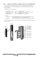
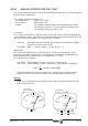
AP.4.2 DIGITAL ELECTRICAL SIGNALS FOR PLC OR MANOEUVER
Four internal boolean variables of the Drive can be taken to the digital outputs offered by
connector X6 of the A1 card. These digital outputs may participate in the maneuver of the
electrical cabinet.
The variables chosen most often are:
Speed lower than Nx SV3 = nFeedbackMinorNx (See SP40)
Command speed reached SV4 = nFeedbackEqualNCommand (See SP41)
Motor stopped SV5 = nFeedbackEqual0 (See SP42)
Torque smaller than Tx TV10 = TGreaterTx (See TP1)
Example:
OP12=TV10 The contact between pins 10/11 will be closed if the motor torque
exceeds the threshold value Tx set by parameter TP1.
OP10=SV5 The contact between pins 6/7 will be closed if the motor is stopped.
Check the EM chapter of this manual in order not to exceed the electrical limitations for these
electrical contacts.
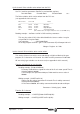
(OP13 -F01407-)
(OP12 -F01406-)
(OP11 -F01405-)
(OP10 -F01404-)
IN 4
IN 3
IN 2
(IP13 -F00904-)
(IP12 -F00903-)
(IP11 -F00902-)
(IP10 -F00901-)
OUT 4
OUT 3
OUT 2
OUT 1
REF-IN
IN 1
1
13
7
6
3
5
4
8
2
1
9
11
13
12
10
Pin
(Phoenix,
3.5 mm)
X6-DIGITAL I/Os
A1
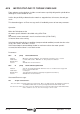
1
1
X7-ANALOG I/Os X6-DIGITAL I/Os
P2P1
(A1 Board)