
Specifications


Applications Ver. 0002 AP - 25
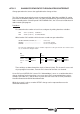
;---------- AUXEND, /XFERINH, /FEEDHOLD ---------
;
DFU STROBE OR DFU TSTROBE
OR DFU T2STROBE OR DFU MSTROBE
= TG1 1 100 ; confirmation pulse STROBES
;
NOT T1
AND NOT M150 ; Gear change in progress at the drive
= AUXEND ; M,S,T functions being executed
;
NOT M241 AND NOT M242 ; Gear change in progress at the drive
= /XFERINH ; Locked CNC block reading
= /FEEDHOLD ; Feedhold for CNC axes
;
END
AP.3.2.3 EXAMPLE OF A PLC PROGRAM FOR A PARAMETER SET
CHANGE
This example shows how to work with in both spindle and "C" axis mode with the same drive.
The drive of the main spindle (S) is identified as number 3 in the Sercos ring.
At the drive.
A different parameter set must be defined (it must be the last set -7- for the "C" axis ). In
the "C" axis mode, the machine must be forced to work in the lowest range (greater gear
ratio) and indicate it to the Drive (Gear Ratio 0).
Set: GP4 = 8 (to make it possible to activate set 7)
GP6 = 1 (to only work with Gear Ratio 0, in this example).
Two tables must be defined at the CNC:
Spindle table. SERCOSID = 3
"C" axis table. Spindle in closed loop working as a regular axis.
Set the external feedback (SERCOSLE=0) with all the necessary
parameters. SERCOSID = 3
Important:
When using the same motor as "C" axis or as a spindle, both CNC tables must have the
same SERCOSID parameter value.
Set PLC parameter P28(SRR700) = 3.33172.
(The number 33172 is the SERCOS identifier of variable DV11 (F-404))
This way, register R700 (associated with parameter P28) will contain the DV11 -F00404-
variable "FagorDiagnostics" of the main spindle making it possible to know variables
"ActualParameterSet" (GV21) and "ActualGearRatio" (GV25) through it.