
Specifications


AP - 10 Applications Ver. 0002
AP.1.2 CONSIDERATIONS AT THE DRIVES
When using the Sercos interface, certain Drive parameters are no longer needed.
If neither the "Encoder Simulation" nor the "I/O" boards are installed, their associated
parameters are not needed either.
Parameters NP121 -S00121-, NP122 -S00122- and NP123 -S00123- must be properly set
in the following cases:
- At the axis drives, ALWAYS.
- At the spindle drives, when wishing to display tool speed or to work in closed loop (M19
or Rigid Tapping) while working with motor feedback (SERCOSLE=1).
At the spindle drives with external feedback (SERCOSLE=0) the NP parameters need not be
set.
SP20 -F00031- and SP21 -F00081- must be set:
- At the spindle drives, ALWAYS. Set them with the maximum motor speed values for
that application and 9500 millivolts respectively.
- They need not be set at the axis drives.
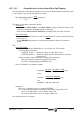
Example for setting parameters NP121, NP122 and NP123:
If for every 5 turns of the motor shaft, the ballscrew turns 3 times. The parameters must
be set as follows:
NP121 = 5 NP122 = 3
If it is a linear axis where for each ballscrew turn, the table moves 4 mm:
NP123 = 40000 tenths of a micron.
If it is a rotary axis where each turn of the output pulley means a 360º turn:
NP123 = 3600000 ten-thousandths of a degree.
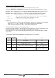
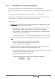
For example:
Motor
Speed
Motor
Speed
INPUT PULLEY
OUTPUT PULLEY
BALLSCREW
TABLE
Example:
Diameter of the output pulley = 25.75 mm
Diameter of the input pulley = 15.3 mm
NP121 = 2575
NP122 = 1530
Gear ratio =2575/1530 =1.683
Ballscrew pitch = 5 mm
NP123 = 5 milimeters