
Specifications


AP - 2 Applications Ver. 0002
AP.1.1 CONSIDERATIONS AT THE 8050/55 CNC
When using the Sercos interface, the Drives must be identified in the ring and determine the
operation mode.
Certain CNC 50/55 and Drive parameters must also be set.
AP.1.1.1 IDENTIFICATION AND OPERATION MODE
The following CNC parameters must be set for each servo drive.
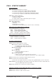
SERCOSID (Parameters: P056 for the axes, P044 for the spindles, P044 for the auxiliary spindle)
Function: Identifies each Drive in the Sercos ring. Its value must match the selection at the
Node_Select switch.
Possible values: 0 The Drive is "transparent" in the communications within the ring; but it is
not recognized as one of its elements.
1..8 The Drive is identified in the ring with the SERCOSID element number ,
and will have all the features of the Sercos interface.
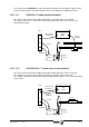
Example: See illustration.
SERCOSLE (Parameters: P063 for the axes, P051 for the spindles)
Function: Determines the feedback source at this servo drive system. In other words, if the
CNC receives the feedback from that servo system through its connector at the axes
module or through the Sercos interface. In either case, the velocity command is sent
out to the drives via Sercos.
Possible values: 0 (Mode 0) The servo system has an encoder or scale outside the motor
and the CNC 50/55 receives the signals through the corresponding
connector at its axes module.
1 (Mode 1) The CNC 50/55 receives the feedback position from the Drive
through the Sercos ring. This Drive has generated that signal based on the
motor feedback itself.
Important:
The value of the SERCOSID parameter must match the address selected with the
"Node Select" switch at the Drive module.
Remember that the numbers must be correlative and starting from One.
If the same motor is to be used as "C axis" and as spindle, the SERCOSID
parameter of both CNC 50/55 tables must have the same value.
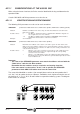
The servo drive identified as number 1 (for example) does not have to correspond to the X
axis, the Y axis to another and so on. However, it would be much simpler to make the axes of
the machine X, Y, Z, U, V, W, A, B and C follow a sequential numbering system. The diagram
below shows an example.