
Specifications


Positioning Drive Setup Ver. 0002 PSU - 17
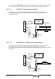
Various parameters for the position loop.
PP49, PP50: Indicate the maximum position that can be reached by the servo system in both positive and
negative directions respectively. These limits are observed only when all the position data is referred to
Machine Reference Zero. That is, Bit 0 of PV203 -S403- PositionFeedbackStatus is set to "1".
If the variable PV58 -S258 TargetPosition exceeds the position limits, the drive will activate bit 13 of
DV9 -S12- Class2Diagnostics (Warnings) TargetPositionOutsideTheTravelZone.
The CNC also observes the travel limits defined in its axis parameter tables.
PP55: Controls the polarity of various position data.
Bit 4: Position limits
= 0 active (by default). See PP49 and PP50.
= 1 cancels the position limits.
Bit 3: Direct position feedback value
= 0 non-inverted
= 1 inverted (by default)
Bit 2: Motor position feedback value
= 0 non-inverted
= 1 inverted (by default)
Bit 0: Position commandvalue
= 0 non-inverted
= 1 inverted (by default)
PP58: Ballscrew error. With motor feedback, the drive compensates for the backlash in changing direction.
Both the drive and the CNC offer parameters to set the value of the ballscrew backlash; but this value must
only be registered in either one of them. The other parameter must be set to "0".
PP76: Command application in module format. Verify that the CNC defines that axis the same way (module
or absolute format).
Bit 7: = 0 The module format is not applied.
= 1 The module format is applied to the axis.
PP103 : Value of the module to be applied on to rotary axes that do not work as linear axes (usually 360º).
QP1 : Loop cycle time. Read-only parameter that indicates how often the loop is being closed at the drives.
Parameters to be used only in Motion Control applications.
PP57: In-position zone. It indicates the difference allowed between the real and final position
(PV58 -S258- TargetPosition) for considering that the axis is in position.