
Specifications


Positioning Drive Setup Ver. 0002 PSU - 3
PSU.2 DIRECT FEEDBACK
The position feedback may be mounted directly on the moving load. From now on, this will be
referred to as "Direct Feedback".
To work with direct feedback,
- Take the signal to connector X3 of the drive.
- activate bit 2 of parameter AP1 -S32-.
- indicate to the Drive the type of feedback device and the type of signal using these
parameters:
GP10 -F234- Feedback2Type
NP117 -S117- ResolutionOfFeedback2
PP115 -S115- PositionFeedback2Type
To work with motor feedback,
- take the signal to connector X4 of the drive.
- deactivate bit 2 of parameter AP1 -S32-.
- indicate to the Drive the type of feedback device and the type of signal using these
parameters:
GP2 -F701- Feedback1Type
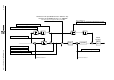
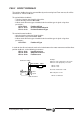
In order for the drive to know the mechanical ratio between the motor movement and the direct
position feedback, set the following parameters:
NP121 -S121- InputRevolutions
NP122 -S122- OutputRevolutions
NP123 -S123- FeedConstant
Motor
Speed
Motor
Speed
INPUT PULLEY
OUTPUT PULLEY
BALLSCREW
TABLE
Example:
Diameter of the output pulley = 25.75 mm
Diameter of the input pulley = 15.3 mm
NP121 = 2575
NP122 = 1530
Gear ratio =2575/1530 =1.683
Ballscrew pitch = 5 mm
NP123 = 5 milimeters