
Specifications


Positioning Drive Setup Ver. 0002 PSU - 1
PSU. POSITION DRIVE SETUP
This chapter describes some characteristic aspects for setting up the DDS module when
using it as a "Position Drive". The previous SSU chapter describes the necessary steps for
setting up a "Velocity Drive".
The last section summarizes step by step the Drive setup procedure.
The "Position Drive" is the result of integrating a "Velocity Drive" and a "position control loop".
Thus, the documentation for the "Velocity Drive" can also be used here.
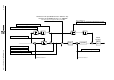
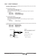
PSU.1 POSITION LOOP
From software version 04.01 on, the Drive is capable of closing the position loop and,
therefore, attend to positioning commands. The position loop consists of a Proportional control
and a Feedforward Derivative control. See diagram.
The position feedback may be taken from the motor feedback or from a feedback located on
the load (direct feedback).
First of all, the operating mode of the Drive must be determined with parameter AP1 -S32-:
- whether the position feedback is on the motor or on the load.
- the motor feedback will be connected to connector X4 of the drive.
- the feedback signal on the load (direct feedback) will go to connector X3 of the
drive.
- whether Feedforward will be applied in the position loop or not.
The position loop also offers a parameter for controlling the ballscrew backlash and, in rotary
movement, it can handle the command in module format.