
Specifications


Velocity Drive Setup Ver. 0002 SSU - 5
X7(11)
X7(10)
X7(9)
X7(8)
Variable examples for OP1 and OP2
SV2 -S00040-
VelocityFeedback
SV7 -F01612-
VelocityCommandFinal
TV1 -S00080-
TorqueCommand
TV2 -S00084-
TorqueFeedback
CV3 -F00311-
CurrentFeedback
.... and more
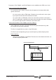
Physical Analog Outputs
D/A
OP1 -F01400-
DA1IDN
OP3 -F01402-
DA1ValuePer10Volts
Ref
±10 Volts
max.
OP2 -F01401-
DA2IDN
OP4 -F01403-
DA2ValuePer10Volts
OV1 -F01408-
DA1Value
OV2 -F01409-
DA2Value
Channel 1
Channel 2
D/A
Ref
1
13
1
11
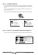
X7
P2
P1
(Phoenix,
3.5mm)
X6
(Phoenix,
3.5mm)
SSU.4 ANALOG OUTPUTS
The DDS module has two analog outputs at connector X7 between pins 10 and 11 (channel 1)
and pins 8 and 9 (channel 2) which can be programmed for displaying the various internal
variable of the drive. Anyway, the most common ones are:
1.- Velocity loop 2.- Torque parameters
3.- Rotor sensor 4.- Encoder simulator
5.- Function generator.
The variables are selected by means of parameters OP1 -F01400- and OP2 -F01401-.
OP3 -F01403- and OP4 -F01404- set the values of these variables corresponding to an
analog output voltage of 10 Vdc. The modification of these variables has an immediate effect
(on line). To keep the values of these parameters, they have to be saved into Flash memory.
Analog outputs as adjustment tools.
With an oscilloscope connected to these analog outputs, it is possible to monitor those
internal variables of the Drive and check overshooting, stabilizing times, accelerations, system
stability, etc.
For example, to display the torque and instant speed signals:
OP1=SV2 Actual speed via channel 1, pins 10/11 of connector X7
OP2=TV2 Actual torque via channel 2, pins 8/9 of connector X7
OP3=100 (100 rpm / 10 volts)
OP4=1 (1 deciNm / 10 volts)