
Specifications


SSU - 4 Velocity Drive Setup Ver. 0002
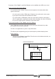
SSU.3.3 COUNTING DIRECTION
For the turning direction of the diagram below (clockwise), the encoder simulator generates
the A signal 90° ahead of the B signal when parameter EP3 -F00502- has its default value
EP3 = 0.
If EP3 = 1, the simulator will generate the B signal 90° ahead of the A signal for the same
turning direction of the motor.
Obviously, the opposite turning direction (counterclockwise) inverts the order of the signals.
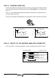
SSU.3.4 PIN-OUT OF THE ENCODER SIMULATOR CONNECTOR
Drive connector X3 is the one outputting the signals generated by the encoder simulator.
EP1 -F500-
EncoderSimulatorPulsesPerTurn
EP2 -F501-
EncoderSimulatorI0Position
EP3 -F502-
EncoderSimulatorDirection
A
A
B
B
Io
Io
X3(1)
X3(2)
X3(3)
X3(4)
X3(5)
X3(6)
HV2-X3 Board Id
Encoder Simulator
X3(11)
GND
90° PHASE-SHIFT
A
Io
B
t
90° PHASE-SHIFT
A
Io
B
t
EP3 = 1EP3 = 0
CLOCKWISE TURN