
Specifications


Velocity Drive Setup Ver. 0002 SSU - 1
SSU. VELOCITY DRIVE SETUP
This chapter describes the setup procedure for DDS drive module when used as "Velocity
Drive". The necessary steps for the application as "Position Drive" are described in the next
PSU chapter.
SSU.1 ADJUSTMENT OF THE OFFSET OF THE ANALOG SIGNAL
Power the Drive on. The next step is to eliminate the possible offset of the analog command.
When using Sercos interface, this section is not applicable.
Send 0V command to the drive. Monitor the motor speed at the CNC or by "watching" the
SV2 -S00040-. Assign values to the offset parameter SP30 -F01603-, (with the opposite sign
of SV2 -S00040-) until the motor stops completely. But, careful, this way, only the drive's
offset is eliminated, the CNC may have another offset. Now adjust the CNC offset.
To adjust the offset of the whole control loop, get the CNC in dro mode but with the
“Drive_Enable” and “Speed_Enable” active, give values to SP30 -F01603- until the motor
stops. Another procedure may be to set a position for the axis with the CNC and adjust
SP30 -F01603- until the following error is symmetrical (same in both directions).
After having determined the proper value, the result has to be Saved into Flash memory and
the unit must be Reset. Procedure explained in the GSU chapter.
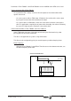
Apart from this adjustment mechanism, there is a potentiometer (See drawing, P1) designed
so the user can correct the slight drifts suffered by the electrical components with time.
Same for Analog input 2
with SP31 -F01604- and P2.
X7(3)
X7(2)
IP1=2
IP1=1
IV1 -F00905-
IV2 -F00906-
SP30
-F01603-
P2
P1
Analog Input 1
X7(5)
X7(4)
1
13
1
11
X7
P2
P1
(Phoenix,
3.5mm)
X6
(Phoenix,
3.5mm)
SP31
-F01604-
IP1
-F00900-
Analog Input 2