
Specifications


Common Setup Ver. 0002 GSU - 1
GSU. COMMON SETUP
This chapter describes some of the steps of the adjustment process for the drive module
DDS. It only considers the ones that are common to the "Velocity drive" and "Position drive"
applications. The specific steps of each application are described in the following SSU and
PSU chapters.
GSU.1 MODULE POWER-UP
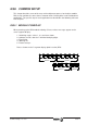
When powering up the DDS module or doing a Reset, various messages appear on the
seven-segment display:
1.- Initializing stages: values 1, 2, 3 and 4 are shown.
2.- Software version, after the "r" with the identifying digits.
3.- Error listing.
4.- Warning list.
5.- Return to step 3.
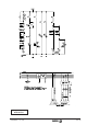
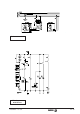
Phases shown on the 7-segment display (04.01 version) DDS
PHASE 2
PHASE 3
PHASE 1
PHASE 4