
Specifications


Installation Ver. 0002 IN - 31
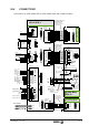
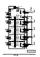
This circuit configuration joins the error reset and the system power-up in a single push-
button.
Activating D2 activates the relay D3 which in turn confirms the Drive_Enables of all drive
modules. The green and red lamps indicate that there is or not motor torque (Drive_Enable).
When activating the System_Speed_Enable signal of the power supply, the D2 contact is
executed.
Now, the CNC may enable each axis (CNC_Enable) and confirm the Speed_Enable signal to
each drive by means of D4, D5, D6 and D7. Remember that a drive will only respond to an
external velocity command when the Drive_Enable, Speed_Enable and
System_Speed_Enable signals are active (24 Vdc).
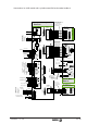
Stop. When D1 is deactivated on the emergency line or the OFF button is pressed, K1 is
deactivated and the power supply loses its three-phase power. The System_Speed_Enable
signal drops and, with zero velocity command, the motors try to stop.
To obtain a controlled stop, with torque:
- the drives' control circuits must be under power and
- the Drive_Enable signal must remain active while braking the motor.
These two points are obtained:
- using a 24Vdc power supply that maintains those 24Vdc by using the energy returned by
the motor to the power bus. The auxiliary power supply APS 24, as well as the internal
power supplies of the XPS, PS-25B, and compact modules meet this condition. (24 Vdc
(*) on the diagrams)
- delaying the cancelling of D3 and using a maintained 24Vdc voltage to activate the
Drive_Enable pin shown with an asterisk (*) on the diagram.
When opening Q1, the braking must also be controlled.
Controlling the brake. In some applications, the Z axis on a milling machine, a
electromechanical brake is used over the rotor in order to lock it.
The brake holds the rotor when it loses voltage at its terminals. Therefore, when the machine
is down, the brake locks the Z axis so it does not drop. The reaction time of a brake may be
anywhere from 200 ms to several seconds.
While the brake is locking the motor, the motor must be kept with torque. To do this, the drive
has parameter GP9 -S00207- DriveOffDelayTime. This GP9 indicates how long the drive will
maintain its torque active after stopping the motor (speed ~ 0) . GP9 -S00207- is given in
milliseconds. By assigning to GP9 a value slightly larger than the brake holding time, one
assures that the axis does not drop in emergency stops.
When powering the machine up, the brake must not be released until the system assumes
control of that axis. This can also be controlled by means of internal variable
TV100 -F01702- TorqueStatus.