
Specifications


Installation Ver. 0002 IN - 29
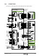
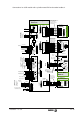
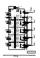
Connection of an SCD module with a spindle motor SPM and encoder feedback.
X2
IN
OUT
X2
1
10
(Phoenix, 5.08mm)
IN
OUT
NODE
SELECT
4
0
8
Di
g
ital S
p
indle Com
p
act Drive
SCD 2.50 ...
7
6
3
5
4
8
2
1
SPEED ENABLE
DRIVE ENABLE
DR. O.K.
9
10
PROG. OUT
ERROR RESET
+24 Vdc
0 V.
L1
L2
L3
POWER MAINS
Ri
Re
L+
External Ballast
X1
3
(Phoenix,
7.62 mm)
1
2
3
1
X1
L1
L2
May be connected
in any order.
380 / 460 Vac
1 Amp
(T) Fuses
Must be greater than
Internal Ballast Resistor.
POWER MAINS
May be connected
in any order.
2 x 380-460 Vac
Internal
use.
MPC-4x...
110 mA máx
OP5
5
4
3
2
1
10
9
8
7
6
11
-15v
+15v
5
4
3
2
1
9
8
7
6
+15vdc
-15vdc
X7
X6
13
12
11
10
A1 Board
P2
P1
Programmable
Inputs (24Vdc)
Programmable
Outputs
(24V-1Amp.)
New !!
IN-1
IN-2
IN-3
IN-4
OUT-1
OUT-2
OUT-3
OUT-4
Analo
g
Output 1
(-)
(+)
IV2
IV1
OP2
OP1
(-)
(+)
Analo
g
Output 2
(-)
(+)
(-)
(+)
OP4
OP3
OP13
OP10
IP10
IP13
OP12
OP11
IP11
IP12
OV2
OV1
U
1
2
3
4
A
/A
B
/B
5
6
7
8
Io
/Io
11
0 V
X3
(HD, Sub-D, F15)
Read
y
Made Cable to CNC
SEC 1/3/5/10/15/20
(Len
g
th in meters;
includin
g
connectors)
Encoder
Simulator
(Option)
Reserv.
Reserv.
1
5
11
15
(HD,
Sub-D,
M15)
X3
2
3
4
RxD
TxD
GND
Serial Line
Interface
Board
(Sub-D, F9)
5
+5V
1
5
6
9
(Sub-D, F9)
X5
1
5
6
9
(Sub-D, M9)
X5
RxD
TxD
GND
+5V
2
3
4
5
PC-Computer or
Pro
g
rammin
g
Module
1
2
3
4
5
6
7
8
11
(Sub-D, M15)
8
1
15
9
(Sub-D,F15)
MPC-4x...
MPC-4x...+2x1
V
W
S
p
indle Motor
SPM...E...
Fagor CNC
Wire necessar
y
onl
y
when usin
g
the Pro
g
rammin
g
Module.
M
3
Holding Brake
(Option)
U1
V1
W1
X3
Electric Fan
X1
220 Vac
50 Hz
N.C. Thermal
Switch (150°C)
220Vac Released
0V Holding
220 Vac
50 Hz
Star
Connection
U1
V1
W1
Cable 4x2x0,14+2x0,5
Read
y
Made Cables
(Sub-D, M9)
PTC
E0C 12
(HD, Sub-D, M26)
X4
X4
9
1
26
19
(HD,
Sub-D,
F26)
Blue
Gre
y
Green
Brown
Purple
Pink
White
Red
20
19
11
2
10
1
21
22
Read
y
Made Cable
EEC 5/10/15/20/25
(Len
g
th in meters;
includin
g
connectors)
10
2
6
5
1
8
3
4
26
25
12
REFCOS
SIN
REFSIN
+485
-485
GND
TEMP
TEMP
+8V
COS
7
23
X2
Yellow
Black
9
1
2
3
4
11
1012
7
8
6
5
9
Front View
ENCODER
Cable 4x2x0,14 + 2x0,5
Green
Yellow
Blue
Purple
Gre
y
Pink
Brown
White
Black
1
13
1
11
X7
P2
P1
(Phoenix, 3.5mm)
(Phoenix, 3.5mm)
Analog Input 2
Analog Input 1
X6