
Specifications


Installation Ver. 0002 IN - 25
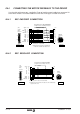
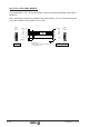
IN.7.5 SERIAL LINE CONNECTION
To transfer the parameter table and set up the system, the drive must be connected to a PC-
compatible computer or with the Programming Module "DDS PROG MODULE" through a
serial line.
The metal shield must be soldered to the hood of the connector at the Drive end. The pins
labeled as "Reserved" in the drawings MUST NOT be connected anywhere by the operator.
Serial line to a PC.
If the PC has more than one serial port, it must be selected by means of the setup window of
the communication program WinDDSSetup. See the GSU chapter
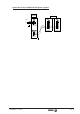
The "serial port" of the PC may be accessible through either a 9-pin or a 25-pin SUB-D type
connector.
8
6
4
3
2
1
5
Pin
Overall shield.
Metallic shield connected to CHASSIS pin
- only at the Drive end -
(Sub-D,
F25)
Front View
8
6
4
3
2
1
5
Pin
CTS
DSR
DTR
TxD
RxD
FG
GND
Si
g
nal
CHASSIS
1
5
(Sub-D,
F9)
Front View
6
9
to DRIVE -X5-
CTS
DSR
DTR
TxD
RxD
FG
GND
Si
g
nal
1
5
(Sub-D,
F9)
Front View
6
9
to PC
8
6
4
3
2
1
5
Pin
5
6
20
3
2
1
7
Pin
CTS
DSR
DTR
TxD
RxD
FG
GND
Si
g
nal
CHASSIS
1
5
(Sub-D,
F9)
Front View
6
9
CTS
DSR
DTR
TxD
RxD
FG
GND
Si
g
nal
1
13
14
25