
Specifications


IN - 24 Installation Ver. 0002
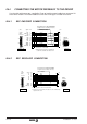
IN.7.4 SERCOS CONNECTION
Identification.
Distinguish each Drive by means of the 16-position rotary switch (Node_Select) with
sequential numbers starting from One. After any change at the Node_Select switch, the
module has to be reset for the change is assumed.
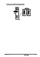
Important:
Give to the SERCOSIS parameters of the CNC the same id numbers as the ones
assigned by means of the Node_Select switch. See drawing.
If the same motor is to be used as "C" axis and "spindle", the two CNC tables must have
the same value for the SERCOSID parameter.
If the Zero identifier is assigned to a Drive, that module will be ignored, even when the ring
stays closed for all purpose for the rest of the elements. That drive may receive the velocity
command in an analog way and can be adjusted through the serial line.
Important:
For example, a system with four drives identified as 1,2,3,4. If we wish to ignore the
second one, we must renumber some of the other ones so they are sequential. The
easiest way would be: 1,0,3,2.
Remember that the SERCOSID parameters of the CNC can also be modified the same
way.
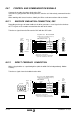
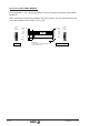
Interconnection.
Connect in the Sercos ring all the drives that will be governed by the CNC.
Connect, with each fiber optic line, an OUT terminal with another IN terminal. See drawing.
Each Drive comes with a fiber optic line to connect it to the adjacent module. Fagor provides
the other necessary fiber optic lines upon request.
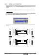
If the machine has two separate servo drive systems (each with its own power supply) and a
single CNC, the same ring must interconnect all the drives of the machine.