
Specifications


IN - 22 Installation Ver. 0002
IN.7 CONTROL AND COMMUNICATION SIGNALS
Connect the encoder simulator signal to the CNC.
If the Drive is going to work with analog interface, take the ±10 Vdc velocity command from the
CNC.
When working with Sercos interface, identify the Drives and connect them with each other.
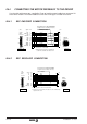
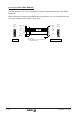
IN.7.1 ENCODER SIMULATION CONNECTION, SEC
Depending on the type of motor feedback, the drive generates a set of signals that simulate
the TTL signals of an encoder mounted onto the rotor of the motor.
Take these signals from the Drive to the CNC with the SEC cable.
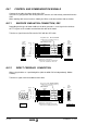
IN.7.2 DIRECT FEEDBACK CONNECTION
When using the drive as a positioning drive (with the 8070 CNC or independently -Motion
Control-).
Take these signals from the feedback to the drive.
Yellow
Purple
Blue
Grey
Green
Brown
Pink
Black
White
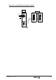
Ready Made Cable SEC 1/3/5/10/15/20
(Len
g
th in meters; includin
g
connectors)
6
5
4
3
2
1
7
8
Cable 4x2x0,14 + 2x0,5
11
Pin
Twisted pair. Overall shield.
Metallic shield connected to CHASSIS pin
- at the CNC end and at the Drive end -
8
1
15
9
(Sub-D,
M15)
Front View
6
5
4
3
2
1
7
8
11
Pin
/Io
Io
/B
B
/A
A
AL
/AL
GND
Si
g
nal
CHASSIS
1
5
(HD,
Sub-D,
F15)
Front View
11
15
to DRIVE -X3-to CNC
Yellow
Blue
Grey
Green
Brown
Red
Pink
White
Fa
g
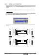
or Sensor Cable EC-PD 1/3/6/9/12
(Len
g
th in meters; includin
g
connectors)
6
5
4
2
1
7
8
Cable 4x2x0,14
9
Pin
Twisted pair. Overall shield.
Metallic shield connected to Chassis pin
- at the Sensor end and at the Drive end -
81
Front View
6
11
2
9
Pin
/Io
Io
/B
B
/A
A
+5Vdc
Si
g
nal
1
5
(HD,
Sub-D,
M15)
Front View
15
11
to DRIVE -X3-
to Feedback
Sensor
GND
1
5
4
3
2
4
5
6
7
9
15