
Specifications


Installation Ver. 0002 IN - 19
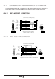
IN.5 BRAKE CONTROL
To govern the mechanical brake optionally incorporated on some motors, they have to be
supplied with:
- 24 Vdc, for FXM -axis motors-
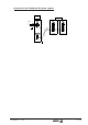
- 220 Vac for SPM -spindle motors-.
The consumption power of the brakes is indicated on chapters SM and AM.
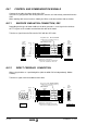
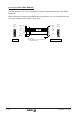
A simple transformer-rectifier circuit like the one below should be enough to power the FXM
motor brake.
Applying the indicated voltages releases the motor shaft.
When installing the motor, verify that the brake fully releases the shaft
before turning it for the first time.
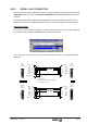
The 24 Vdc generated by modules like the PS-25B, APS 24 or XPS, or that
being generated by another power supply handles the control signals of
the drive MUST NEVER be used to also control these brakes.
These brakes generate voltage peaks that can damage the drive.
On the FXM, watch that no voltage over 26 V is applied which would
prevent the shaft from turning.
220/24
24 Vdc
220 Vac
Holdin
g
Brake
(Option)
MC 23, MC-46
or MC 80 socket
MPC-4x...(mm
2
)+2x1
F
E
-
+
24V Released
0V Holdin
g
Read
y
Made Cables
Holdin
g
Brake
(Option)
220Vac Released
0V Holdin
g
220 Vac
50 Hz
+
-
MC 23 or
MC 46 socket.
E
DA
CB
F
220 Vac
FXM MOTOR
SPM MOTOR