
Specifications


IN - 18 Installation Ver. 0002
IN.4 CONNECTING THE MOTOR FEEDBACK TO THE DRIVER
Use the cable with connectors supplied by Fagor to lead the motor feedback to connector X4
of the Drive module. The motor feedback can be one of two types: encoder or resolver.
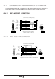
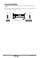
IN.4.1 EEC ENCODER CONNECTION
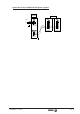
IN.4.2 REC RESOLVER CONNECTION
9
1
26
19
(HD,
Sub-D,
M26)
Blue
Grey
Green
Brown
Purple
Pink
White
Red
Ready Made Cable EEC 5/10/15/20/25
(Length in meters; including connectors)
10
2
6
5
1
8
3
4
12
REFCOS
SIN
REFSIN
+485
-485
GND
TEMP
TEMP
+8V
COS
7
20
19
11
2
10
1
21
22
26
25
23
Yellow
Black
9
Cable 4x2x0,14 + 2x0,5
Signal Pin Pin
Twisted pair. Overall shield.
Metallic shield connected to CHASSIS pin
- at the Drive end and at the Motor end -
CHASSIS
E0C 12
1
2
3
4
11
1012
7
8
6
5
9
Front View
Front View
to DRIVE -X4- to MOTOR
6
5
4
3
2
1
7
8
Ready Made Cable
REC 5/10/15/20/25
(Length in meters; including connectors)
16
7
18
9
17
8
21
22
26
R2
R1
S2
S4
S3
S1
Blue
Red
Green
Black
Black
Black
White
Black
R0C 9
1
2
3
4
7
8
6
5
9
Front View
Cable 4x2x0,25
TEMP
TEMP
CHASSIS
Signal Pin Pin
9
1
26
19
(HD,
Sub-D,
M26)
Front View
Shielded by pairs of cables, and overall shield.
All shields interconnected and connected to the same CHASSIS pin.
- only at the Drive end -
to DRIVE -X4- to MOTOR