
Specifications


Installation Ver. 0002 IN - 13
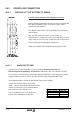
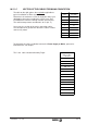
IN.3.2 MOTOR/DRIVE CONNECTION
When connecting the Drive module with its corresponding motor, connect
terminal "U" of the drive module with the terminal corresponding to the
"U" phase of the motor.
Same as terminals "V-V", "W-W" and "Ground-Ground".
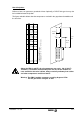
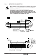
In order for the system to comply with the European Directive on
Electromagnetic Compatibility, the hose grouping all four cables U-V-W-
Ground must be shielded and must be connected only at the drive end as
shown on the diagrams. These conditions are a must.
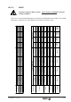
M
3
U
MPC-4x...(mm
2
)MPC-4x...(mm
2
)+2x1
V
W
U1
V1
W1
N.C. Thermal
Switch (150°C)
Star
Connection
U1
V1
W1
Ready Made Cable Ready Made Cable
DRIVE SPM MOTOR
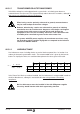
M
3
Holding Brake
(Option)
MC 23, MC 46
or MC 80 socket
MPC-4x...(mm
2
)
MPC-4x...(mm
2
)+2x1
U
V
W
C
F
D
B
E
A
-
+
+24 Vdc
MC 23 or
MC 46 socket.
U
V
W
Ready Made Cables
E
DA
CB
F
DRIVE FXM MOTOR