
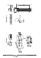
Specifications


Installation Ver. 0002 IN - 1
IN. INSTALLATION
Follow these steps for a complete system installation:
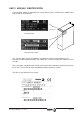
Prepare the supports for the module in the electrical cabinet.
Unpack and mount all the system modules in the electrical cabinet.
Mount the Mains filter in the cabinet.
Electrical interconnection of the Drive system:
- Power Bus bars at the bottom of each module.
- Ground bars at the top and connection of the assembly to the Ground connection.
- Internal bus between the modules powered by the same Power Supply and the power
supply itself.
- Connection to the External Ballast resistor RM-15 or ER if applicable.
Supply voltage. Connection with motors and the CNC:
- Cable hose from mains to the Drive system through the Filter.
- Power cable hose from each Motor to each Drive.
- Feedback cables from each Motor to each Drive.
- Circuit for the control of the Brake.
- Power for the 24Vdc auxiliary power supply from mains (APS 24, XPS or PS-25B).
- Power the control circuits of each drive module with 24 Vdc.
Control and communication signals:
- Encoder simulation cables from each Drive to the CNC if applicable.
- Analog velocity command voltages from the CNC to each Drive.
- Connection of the control signals of the modules, inputs and outputs.
- Sercos connection.
- Identify each system drive with a rotary switch.
- Connect the Modules and the CNC through the fiber optic.
Adjust the modules through the serial line.
In order for the Fagor Servo System to meet the European Directive on
Electromagnetic Compatibility 89/336/CE, the modules installation rules
must be strictly followed regarding:
- The mounting of the Filter to Mains
- Electrical installation of the power stage
. Wiring to mains
. Power connection motor-drive