
Specifications


Electronic Modules Ver. 0002 EM - 45
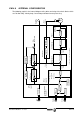
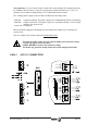
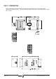
EM.4.8 INTERNAL CONFIGURATION
The following graphic is the internal diagram of the drive consisting of four basic blocks which
are: Position loop, Velocity loop, Current loop and Rotor Sensor processing.
M
3
Velocity
Limit
In
Out
Velocity Loop (*)
A nal og
Input 2
Rotor Sensor
Current Loop
Offset
Correction
A nal og
Input 1
Offset
Correction
Internal
Generator
Error Stop
Ramps
& Jerk
Velocity
Feedback
Current
Limit
Speed PI
Halt Function
SpeedEnable Function
Current PI
Power
Circuits
DriveEnable
Motor
Feedback
Power
Velocity Command
Managment
Error Stop
or
or
Sercos
Interface
Volts/rpm
Ratio
Position
Evaluation
Position to
Speed
S
Sercos
Velocity
Command
Sercos
Position
Command
Velocity Loop (*)
Speed PI
Position Loop
Position P
S
External
Feedback
Position
Feedforward
Velocity
Feedforward
(*) The same Velocity Loop Block
To the
Current Loop