
User Guide


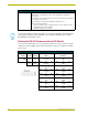
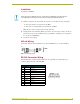
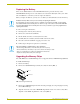
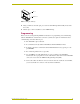

Table Of Contents
Product Information
2
AXC-EM Enhanced Master Card
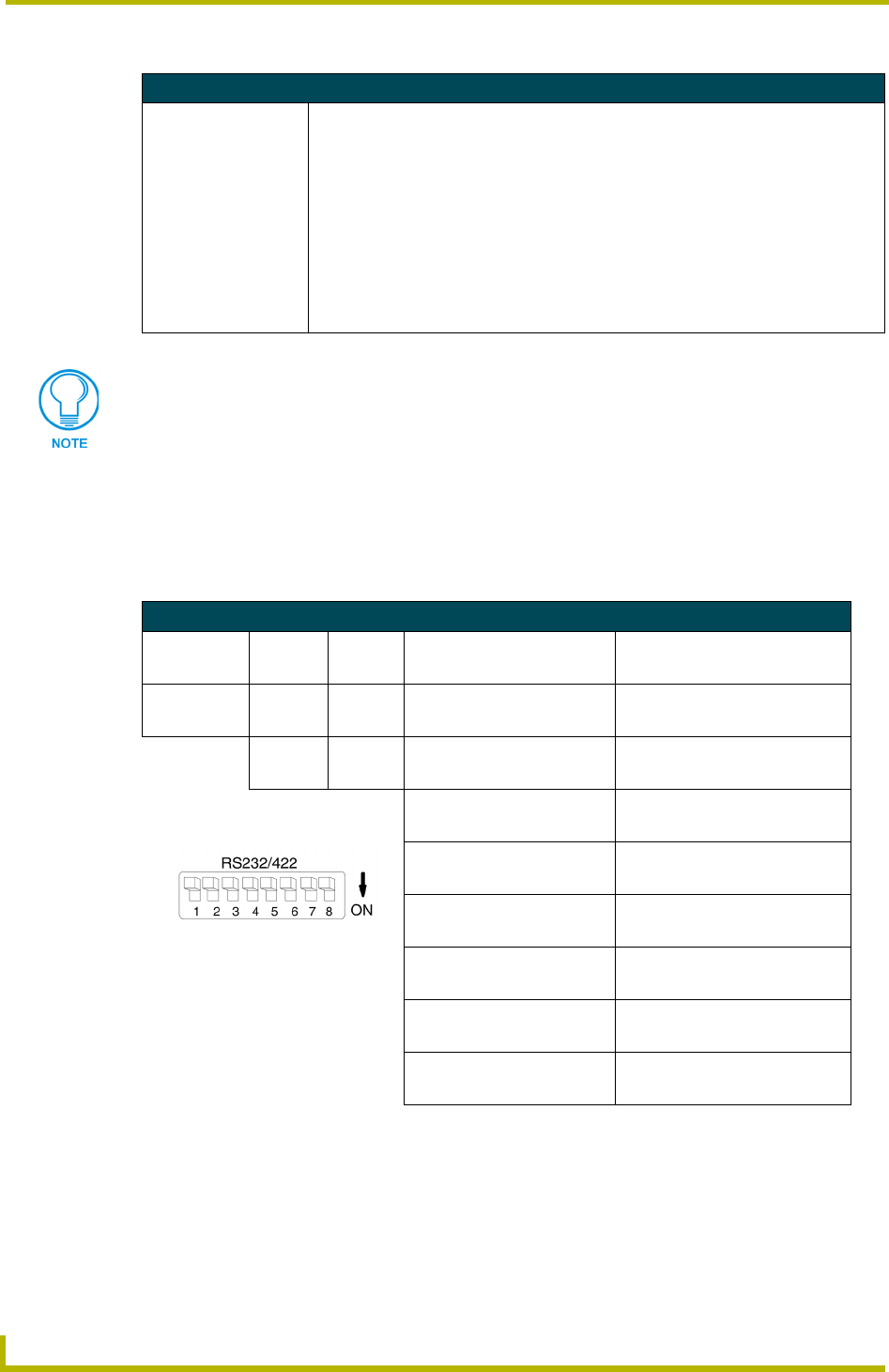
Setting the RS-232 Communications DIP Switch
Use the 8-position DIP switch to set the communication parameters. Set the parameters with the
combination of ON and OFF positions. The following table describes the communications DIP
switch settings:
AXC-EM Specifications (Cont.)
AXlink Status LED The green LED (CR1) on the front end of the card indicates AXlink status, as follows:
• One blink per second indicates power is active and AXlink communication is
functioning.
• Two blinks per second indicate that the devices specified in the master program do
not match the devices found.
• Three blinks per second indicate an AXlink communication error.
• Full on indicates the following:
•There is no AXlink control or activity, but power is on. (For example, another
AXC-EM may have control of AXlink.)
•The Axcess program is not loaded.
To ensure the integrity of your Axcess program, you can use two AXC-EMs, each loaded with the
same program. Should the primary AXC-EM's control of AXlink be interrupted, the secondary
AXC-EM will automatically take control.
Communication Parameters DIP Switch Settings
Switch1 2 3456 7 8
Function Stop Bits Data Bits Parity Baud Rates
Setting Off Off Off Off Off Off Off Off
Value 2 bits 7 bits Unused 300
On On On Off Off On Off Off
1 bit 8 bits Unused 600
Off On Off Off On Off
Unused 1,200
On On Off On On Off
Unused 2,400
Off Off On Off Off On
Mark 4,800
On Off On On Off On
Even 9,600
Off On On Off On On
Odd 19,200
On On On On On On
None 38,400