
Operating instructions
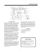
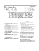

16. Sync Input Loop (BNC) Ð Composite Sync
Input Loop
17. Sync Input (BNC) Ð Composite Sync Input
18. Red Output (BNC) Ð Red Output 714mV
19. Green Output (BNC) Ð Green Output 714mV
20. Blue Output (BNC) Ð Blue Output 714mV
21. Horiz. Sync Output (BNC) Ð Horizontal Sync
Output Ð4Vp-p, 40KHz
22. Vert. Sync Output (BNC) Ð Vertical Sync
Output Ð4Vp-p, 59.49Hz
23. Sync Output (BNC) Ð Composite Sync Output
Ð4 Vpp
24. Monitor Interface Output Ð Positive TTL
Sync Levels. See appendix B for pinout infor-
mation.
25. Remote Control Interface Ð See appendix A
for interface diagrams.
26. Power Input Ð 100-250 VAC, 50/60Hz, 60W
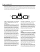
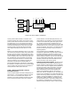
Interface
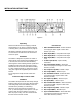
Figure 3 outlines the installation of the VP301
using inputs from:
1. A composite source such as a DVD Laser Disk
Player, VCR or TV Receiver.
2. An S-Video input such as a S-VHS VCR or DVD
3. An RGB input with sync on green or a
Component input such as a DVD player,
Camera or Beta-SP recorder with sync on Y. If
sync on green or sync on Y is not available then
Sync can be interfaced using the Composite
sync input.
All inputs with the exception of the S-Video input
have selectable 75 Ohm input termination switch-
es. These switches are to be in the ON position
unless the unit is being used in a looped configura-
tion. Termination is then located at the last unit in
the loop.
Note: The diagram shows a 5 wire connection to
the monitor/projector, i.e. Red, Green, Blue,
Horizontal Sync and Vertical Sync. For monitors/
projectors with a 4 wire input, use Red, Green,
Blue and Composite Sync outputs.
The monitor/projector will be terminated at 75 Ohm
either internally or by switches located on the mon-
itor/projector.
9
Figure 3