
User manual


Phoenix
32
User Manual www.RealmCtrl.com
3
then you may need to install the ME-260 instead of the NI series controllers. This is
because many Synergy sites make use of the AXcess Master Port Expander (MPE)
controller that allows long AXlink runs from the Head End control system to the
Television Managers that are disbursed throughout the campus. In order for the
MPE to serve as a sub-system of the NetLinx control system, it must be connected
to the ME-260 “Expansion Out” port using a straight-through RJ-11 cable after
having removed the AXcess control card from the MPE and setting the internal
jumper to SPE (Slave Port Expander) mode. Note that a standard telephone cable
will not work as an Expansion Out cable. Rather, the wires must be connected
straight through, pin to pin.
If your facility does not require long AXlink runs and consequently does not require
the MPE then an NI series control system may be used instead. Means of
overcoming AXlink distance limitations are further discussed in Section 11.
Installation of the Head End NetLinx control system entails wiring connections of all
infrared emitters to their associated media sources and display devices, as well as
any relay and RS-232 connections. Also, the outputs of all media devices must be
properly connected to your distribution group(s) (the combiners and/or baseband
routers). This document assumes the reader is well versed in connecting the
control system and will not go into great detail regarding this step.
2.2.2. Step 2: Configure the NetLinx control system communication parameters.
After connecting the NetLinx control system Ethernet port to the network jack or
local router plug, configure the NetLinx control system to acquire a static IP
address. This is necessary so that Phoenix
32
Server will always be able to reach
the NetLinx control system. If you are unable to determine what the static IP
address should be at this time, you may temporarily allow the system to lease an IP
address via DHCP. However, this should be considered temporary until you are
able to confer with the network System Administrator to determine what the static IP
address should be.
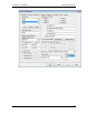
In order to configure the communication parameters, first connect to the NetLinx
Program Port using a DB9 female-to-female cable, or “programming cable.” Then
launch a terminal application such as HyperTerminal and set your communication
parameters to the following:
Baud rate: 115200 (or possibly 38400)
Data Bits: 8
Parity: None
Stop Bits: 1
Flow Control: None
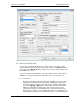
You can determine whether you are properly communicating with the NetLinx
control system by entering a question mark and pressing enter. You should see the
available command set displayed within your terminal window.
Once you are successfully connected, enter the command “SET IP” and follow the
prompts to configure the NetLinx master TCP/IP communication parameters.
2.2.3. Step 3: Set the Head End NetLinx System ID to “1”.
NetLinx control systems are designed with distributed processing capabilities
inherent within the hardware. This allows multiple NetLinx control systems to easily
communicate with one another for sake of distributed processing, overcoming of