
User manual


Phoenix
32
User Manual www.RealmCtrl.com
20
4.5.1.1. When using the Destinations Tab, click the [Input wired to…] drop-down,
then select the output of the combiner or switcher to which the input of the
display device(s) within the destination is connected.
4.5.1.2. When using the Distribution Tab, select the distribution group that the
destination is connected to, then click the [Mapping…] button that is next to
the “Output Count” field. When the Wire Outputs dialog surfaces, select the
output from the distribution group, then select the room to which it connects.
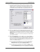
4.5.1.3. When using the Routing Window (which is selectable via the menu item
{Server/Routing Window}), first drag the objects out so that they are visible,
then select {Window/Arrange Icons} so that the Routing Diagram is
comprehensible. Then you may double-click on the distribution group or the
destination and route it using the methods described within sections 4.5.1.2
and 4.5.1.2 above.
4.5.1.4. All new Channels are automatically members of the “All Channels” Category.
New Categories may be created on the Categories Tab (see section 8.5).
Channel categorization applies to the XGen Web Client, discussed in section
10.3. If your facility is not licensed for XGen then categorization is
unnecessary. When assigning Channels to Categories, the changes are
saved immediately. I.e., if you select or deselect a category, the database is
updated instantaneously and there is no need to click [Apply].
4.5.1.5. You may also assign a logo to each channel. By default, the Phoenix logo
will be used. This is another feature that applies to the discrete tuning feature
of the XGen Web Client, discussed in greater detail in section 10.3.3.
4.5.2. Routing of sources is accomplished in much the same manner as routing of
destinations. The exception is that a source input may be routed as well, for sake
of recording and tuning. On the Sources Tab, the source inputs and outputs must
be configured using the [Output wired to/Select] button and the [Input Wired To]
drop-down. As with destination configuration, you may also wire your sources from
the Distribution Tab and/or the Routing Window (see section 4.5.1 above).
4.5.3. Channels are routed in like manner, using either the [Outputs wired to…] button,
or via the Distribution Tab or the Routing Window.
Note: Regardless of the method that you choose when interconnecting the routing
of your facility, it is a good practice to regularly view the Routing Window to help
ensure that the topology you have defined truly mirrors the physical connections of
your system. You may even wish to maximize the Routing Window and leave it in
the background throughout your routing endeavor so that it will visually confirm the
connections as you make them. The Routing Window is a very powerful tool to
assist with visual programming and overviews of the facility configuration. We
recommend that you use it often.
4.5.4. Once you have created your channels, you may go back to the Distribution Tab
and define the Direct Pass Channels (aka “Channel Ring” or “Surf Ring”). Direct
Pass Channels are available to end users at all times. For example, if you create a
Channel called “CNN” and you connect it to input 34 on the combiner, then you add
the “CNN” channel to the Channel Ring, any user within a Destination connected to
the same combiner will be able to access CNN at any time using the handheld
remote control, the Virtual CT5, or the web client (see section 10 for comprehensive
information regarding access to Direct Pass Channels). To add or remove
channels from the Channel Ring, first select the Distribution Group on the