
User manual


Phoenix
32
User Manual www.RealmCtrl.com
15
using the NetLinx naming nomenclature having a Device, a Port, and a System.
The Device portion of the address is the AXlink ID. For AXcess systems, Port will
always be “1”. However, because NetLinx cards allow control of multiple sources
using the same device, the Port may not be “1” if you are using NetLinx control
cards within your Head End. For example, if using an IRS4, which is a NetLinx IR
card that has four outputs, you would enter the proper port (1-4) of the device
having its IR emitter physically connected to the source. The System portion of the
address will always be “1”, which is why it defaults to that value and is disabled.
4.2.6. Configure the digital media server, if applicable. If your facility purchased a license
to control a supported digital file server then the [Configure] button within the
“Digital Media Server” section will be enabled. If the source that you are creating is
a digital media server, click this button to launch the digital media server
configuration dialog, then proceed with configuration of the device. Supplemental
documentation is available regarding configuration and control of digital media
servers.
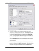
4.2.7. Define the source capabilities: [Play], [Record], and [Tune]. These capabilities
correspond to the capabilities that you want the source to support, which may not
necessarily entail all of the capabilities of the source. For example, if you want to
use a source for recording of off-air media, you might configure it as [Record] and
[Tune] but not [Play], so that the scheduler will never use it when scheduling
standard media events. Of course, to select an unsupported feature (such as
configuring a DVD player as [Record] capable) would be invalid. In such a case,
the NetLinx control system would take no action upon the unit whenever it received
a Record command. In short, you should define all capabilities that the source
supports, unless there is something specific that you would prefer to disallow, in
which case you would not select that capability for the source that you’re
configuring.
4.2.8. VTI-6 Character Generator device ID: The VTI-6 Character Generator (CG) is an
optional add-on that allows user prompts and overlays on the facility display
devices. If you are defining a new system then it is unlikely that the site will include
the VTI-6 CG because the device is obsolete as of the authoring of this document.
However, if you are upgrading an existing Synergy site then the VTI-6 CG may be
present and must be configured on this tab. The information required is:
• The AMX ID. This is the physical AXlink bus address of the VTI-6 CG as defined
by its dip switches.
• The Channel ID. This is the VTI-6 input to which the composite output of the
source is connected. Each unit supports a maximum of 6 channels. VTI-6
Character Generators may be “daisy chained” such that the first channel of the unit
is offset for support of a maximum of 96 CG channels. Be sure that the channel
you enter in Phoenix corresponds to the channel as it is addressed by the
hardware, which may not necessarily correspond to the channel as it is addressed
on the specific VTI-6 on which it resides.
4.2.9. For the time being, ignore the two input fields that regard routing. These are the
[Output wired to/Select] button and the [Input wired to] drop-down. We will
revisit these fields when we interconnect the site routing later.
4.2.10. The only two remaining fields on the Sources tab are the “Installed” date and the
“Usage” fields. These fields cannot be edited as they are maintained entirely by
Phoenix for sake of scheduling and reporting. When scheduling events (covered in
section 5), Phoenix takes many factors into account when selecting a source