
Specifications


4093000 RESEARCH DRIVE, RICHARDSON, TX 75082 • 800.222.0193 • 469.624.7153 fax • TECHNICAL SUPPORT 800.932.6993
© January 2013 AMX. All rights reserved. AMX does not assume responsibility for any errors or omissions.
control system accessoriesUPc20+ control system accessories
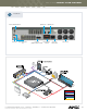
HIGH VOLTAGE TERMINAL BLOCK (P1)
Highvoltageinputandoutputwiringformotororpowercontrol.
LOW VOLTAGE AND CONTROL TERMINAL BLOCK (P2)
Contactclosure,open-collectororCMOSlogiclevelremotecontrolwiring
Inputs5-8arereferencedtothecommonconnectionatpin4
JUMPER JP1
Setscontrolmodeoftheunittocontactclosureorremotesensorserialdata
TEST SWITCHES (PB1 AND PB2)
ProvideslocaloperationofrelaysK1andK2fortestingpowercircuitsormotors
connectedtotherelayterminals.AnLEDindicatesrelaypowerapplied
MOTOR TIME DELAY POTENTIOMETER (R8)
Onlyusedinmotorcontrolmodes.Useradjustedforsettingrelayreleasetime
between0and90seconds
DIP SWITCH (S2)
Providesselectionofcontrolmodeoptions
CONTROL INPUTS
•4closureinputs;operationdenedbymode
•Motorcontrolmodealternatesbetweenthetimedoperationofthetwo
power relays
•Powercontrolmodeallowsindependentcontrolofbothpowerrelays
CONTROL PORTS
(2)2400Wpowerrelays.Totalcombinedcurrentthroughbothrelaysis20Amps
CERTIFICATIONS
UL,C-UL,CE
ENVIRONMENTAL
Operating/StorageTemperature:55ºC
SPECIFICATIONS
DIMENSIONS (HWD)
•81/2”(101/2”(includingange)x41/2”x23/16”(22cm(27cm(including
ange)x11cmx6cm)
•RU:5
WEIGHT
3lbs(1.4kg)
POWER
•Self-poweredwhenusedwith110/220VACapplications
•Powerinputoptions(forcontrolboard):
-120/240V~,50-60Hz,0.05/0.025A
-12VDC,0.2Amax
•Poweroutputperrelay
-20A@120/240V~,50-60Hz(RESISTIVELOAD)
-6A@277V~,50-60Hz(FLUORESCENTBALLAST)
-1HP@120V~,50-60Hz(INDUCTIVELOAD)
-2HP@240V~,50-60Hz(INDUCTIVELOAD)
TotalCurrentthroughbothrelaysCANNOTexceed20amps
ENCLOSURE
Metalwithblackmattenish,knockoutsforconduit
INPUTS
•4closureinputs,operationdenedbymode
•OneIRremotesensorinput
•MotorControlmodealternatesbetweenthetimedoperationofthetwo
power relays
•PowerControlmodeallowsindependentcontrolofbothpowerrelays
INPUT POWER SWITCH (S1)
•Setthisswitchaccordingtothehighvoltagewiringthatwillbeconnectedto
terminals5and6onP1.
•SetswitchS1tothelineinputvoltagevalueusedbeforeapplyingpowerto
theUPC20+
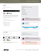
RECOMMENDED ACCESSORIES DESCRIPTION PART # PAGE #
PS2.8 2.8APowerSupply (FG423-05) 412