
Specifications


408 US SALES AND SUPPORT 800.222.0193 • INTERNATIONAL SALES AND SUPPORT +1.469.624.7400 • www.amx.com
© January 2013 AMX. All rights reserved. AMX does not assume responsibility for any errors or omissions.
control system accessories
UPC20+
Universal Power/Motor Controller, 20 A
(110/220 VAC input)
(FG672)
OVERVIEW
Designedforconduitinstallation,theUniversalPower/Motor
Controller,20A(110/220VACinput)isadual20-ampACpower
and motor controller. Configure a wide range of power and motor
control modes for a full range of devices ranging from simple wall
panels with low voltage contact closure to large systems requiring
high voltage contact closure.
The UPC20+ supports two primary operating modes. In Motor
Control Mode, the two relays are automatically activated in
sequencewithanadjustabledelayfrom0to90seconds.Inthis
mode,therearethreecontroloptions:
•Single Button Mode operates with one pushbutton in a
sequence:Up,Stop,Down,Stopandsoonforeachsuccessive
button press.
•Two/Three Button Mode operates with two pushbuttons, one
for Up and one for Down and optionally one for stop.
•Momentary On/Off operates the first relay only while the button
is pressed and then second the relay activates when the button
is released.
In Power Control mode, the UPC20+ provides power control for
two independent circuits with a combined total load of 20 Amps.
Inthismode,therearethreecontroloptions:
•Momentary Power Mode operates the selected relay only while
the button is pressed. The relay is de-activated when the button
is released.
•Latching Power Mode toggles between activating and de-
activating the selected relay on each successive button press.
•Two Button On/Off Mode uses two buttons for each relay, one
to activate and one to deactivate.
FEATURES
•1,2and3-buttonlogicmodes
•LocaltestswitcheswithstatusLEDs
•120,240,and277VACcontrolcapability
•ETLlisted
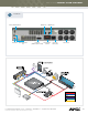
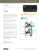
A CLOSER LOOK
75°C INSULATION
USE COPPER ONLY
DISCONNECT SWITCH MAY BE REQUIRED TO DE-ENERGIZE
1
RISK OF ELECTRIC SHOCK - MORE THAN ONE
VOLTAGE PRIOR
POWER TO UNIT
TO APPLYING
IMPORTANT
SWITCH MUST
MATCH INPUT
B
TO CIRCUIT BD
THE EQUIPMENT BEFORE SERVICING
ELECTRONICS
6
5
GND
2
A
K
L
2
1
G
W
K
L
B
1
4
K2
3
W
A
G
2
K1
CAUTION
P1
Richardson, Texas
800-222-0193
UPC20+
469-624-8000
CLASS 2 CIRCUIT ONLY
RECEIVER
ON
PART # 91-0672-01, REV F
+12V
1
P2
21
JP1
SEE INSIDE COVER FOR DETAILED WIRING
NOTE: NO HIGH VOLTAGE THIS CONNECTION
AND DIP SWITCH INFORMATION
IN 4
8
CONTROL
INPUT
INPUTS
GND
3
DATA
2
GND
4
43
IN 1
IN 2
56
IN 3
7
CONTACT
+12
9
REMOTE
C
R
IND.CONT.EQ.
US
LISTED
68WF
PB1PB2
Power Switch
(115/230 VAC)
High voltage
wiring
Spade terminal
block P1
Test switches
with status LEDs
Jumper JP1
DIP switch
IR remote control
connections
HELPFUL HINT
If UPC20+ is powered up when changes are made to Dip Switch set-
tings, then power must be cycled before changes can take effect.