instruction manual AXB-TM5 Television Manager AXlink Bus Controllers
AMX Limited Warranty and Disclaimer AMX Corporation warrants its products to be free of defects in material and workmanship under normal use for three (3) years from the date of purchase from AMX Corporation, with the following exceptions: • Electroluminescent and LCD Control Panels are warranted for three (3) years, except for the display and touch overlay components that are warranted for a period of one (1) year.
Table of Contents Table of Contents Product Information .................................................................................................1 Front Panel........................................................................................................................ 1 Specifications .................................................................................................................... 1 Connection and Wiring .................................................................
Table of Contents ii AXB-TM5 Television Manager
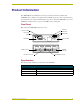
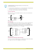
Product Information Product Information The AXB-TM5 Television Manager is a microprocessor-based television controller. The AXB-TM5 can be configured as a peripheral on the AXlink. As part of an Axcess Control System, provides media source selection and management via remote control. The AXB-TM5 acts as a local AXlink bus controller and as a receiver for an AMX wireless control panel. Front Panel FIG. 1 shows the AXB-TM5 front and rear views.
Product Information Specifications (Cont.) Front Panel Components AXlink LED AXlink LED (green and blinks to indicate AXlink communication activity and power: • Full-Off indicates no power is being received or the controller is not • functioning properly. • One blink per second indicates power is active and AXlink communication is • functioning. • Full-On indicates there is no AXlink control or activity, but power is on.
Connection and Wiring Connection and Wiring Device DIP Switch The eight-position Device DIP switch, shown in FIG. 2, sets the AXlink device number. Every device on the bus must have a unique device code. An eight-position DIP switch is used to set the device number for the AXB-TM5. The device number must match the number assigned in the Axcess software program. The AXlink device number range is 1-255 and is sent according to the Device DIP switch positions and their values.
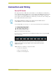
Connection and Wiring Wiring the Rear Panel Preparing/connecting captive wires You will need a wire stripper and flat-blade screwdriver to prepare and connect the captive wires. Never pre-tin wires for compression-type connections. Do not connect power to the AXB-TM5 until the wiring is complete. If you are using power from AXlink, disconnect the wiring from the control system before wiring the AXB-TM5.
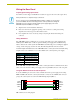
Connection and Wiring CC-IRC emitter wiring connections FIG. 4 shows how to connect a CC-IRC IR Emitter to the IR Emitter connector on the AXB-TM5. CC-IRC Television To emitter GND connector SIG FIG. 4 CC-IRC Emitter wiring connections IR emitter to device installation The following steps describe the installation of the IR emitter to the television IR window. 1. Using a sharp edged tool (knife blade, razor knife, etc.), separate the factory-installed shell as shown in FIG. 5. FIG.
Connection and Wiring For additional information concerning the IR emitter, refer to the IR Sensors and Receivers instruction manual. 4. Attach the IR shield, with IR emitter diode, to the television IR window, ensuring that the IR emitter diode is properly positioned in the television input IR window. 5. Press firmly to activate the pressure-sensitive adhesive of the IR shield. TV sensor connections FIG.
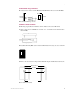
Connection and Wiring PWR GND 12 VDC power supply PWR PWR AXP AXP AXM AXM GND GND FIG. 10 AXlink 12 VDC power supply wiring example If you are using power from AXlink, disconnect the wiring from the Axcess Control System before wiring the AXB-TM5. Use a 12 VDC power supply when the distance between the control system and AXB-TM5 exceeds the limits described in the Wiring Guidelines section on page 4.
Connection and Wiring 8 AXB-TM5 Television Manager
Programming Programming You can program the AXB-TM5 to perform a wide variety of operations using Axcess Send_Commands. This section describes channel settings, IR functions, and system Send_Commands. Refer to the AXCESS Programming Guide for additional programming information. Channel Setting Commands The AXB-TM5 use the channel setting commands listed in the following table.
Programming System Send_Commands System Send_Commands are stored in the Axcess Control System and direct the AXB-TM5 to perform various operations. System Send_Commands Command Description 'CARON' Turns the IR carrier On (default). Example: SEND_COMMAND AXBTMX,'CARON' 'CAROFF' Turns the IR carrier Off. Example: SEND_COMMAND AXBTMX,'CAROFF' 'CH', Generates IR digit pulses to select a television channel number. Channels 1-99 pulse as two digits.
Programming System Send_Commands (Cont.) Command Description 'CTON',
Programming System Send_Commands (Cont.) Command Description '?DE' Sends the current television power sensor (CC-XPS) delay time string ’DE,
Programming System Send_Commands (Cont.) Command Description 'PTOF',
Programming System Send_Commands (Cont.) Command Description 'RO', Sets the offset value subtracted from the IR function before sending the code to the AXC-EM. Syntax: "'RO'," Variables: Offset = 0 through 255 Example: SEND_COMMAND AXBTMX,"'RO',5" Subtracts 5 from the incoming IR code number and sends the appropriate IR function from the AXB-TM5 to the control system. 'SP',' Generates a single function pulse.
Programming System Send_Commands (Cont.) Command Description XCHM Syntax: Changes the IR output pattern for the XCH command. SEND_COMMAND ,'XCH-' Variable: Mode = 0-3 Example: SEND_COMMAND AXBTMX,'XCH 3' Sets the device's extended channel command to mode 3. Mode 0 Example (default): [x] [x] SEND_COMMAND IR_1, 'XCH 3' Transmits the IR code as 3-enter. SEND_COMMAND IR_1, 'XCH 34' Transmits the IR code as 3-4-enter.
brussels • dallas • los angeles • mexico city • philadelphia • shanghai • singapore • tampa • toronto* • york 3000 research drive, richardson, TX 75082 USA • 469.624.8000 • 800.222.0193 • fax 469.624.7153 • technical support 800.932.6993 032-004-1023 6/02 ©2002 AMX Corporation. All rights reserved. AMX, the AMX logo, the building icon, the home icon, and the light bulb icon are all trademarks of AMX Corporation. AMX reserves the right to alter specifications without notice at any time.