
User Guide


Installation and Wiring
6
AXB-TC and AXB-TCR Television Controllers
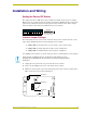
4. Replace the top portion of the enclosure on the bottom portion. Then, refasten the two Phillips-
head screws.
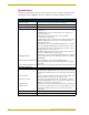
JI jumper settings: TV power sensing/TV power current sensing mode
J2 jumper settings: IR output mode (IR or serial communication)
J3 jumper settings: IR attenuation mode (bypass or adjustment)
JI Jumper Settings: TV Power Sensing/TV Power Current Sensing
Television Power (on or off) Sensing mode To use this mode, connect a CC-IRC to the
television to detect horizontal scan frequen-
cies up to 65 kHz. Place the 2-pin jumper on
the JP1 connector pin's 1 and 2.
Television Power Current Sensing mode To use this mode, connect a PCS Power
Current Sensor to the television to detect on
and off power status. Place the 2-pin jumper
on the JP1 connector pin's 2 and 3. Refer to
the PCS Power Current Sensor instruction
manual for additional control information.
J2 Jumper Settings: IR Output Mode (IR or Serial Communication)
IR Output mode To use this mode, connect a CC-IRC IR
Emitter to the television to transmit IR sig-
nals. Place the 2-pin jumper on the JP2 con-
nector pin's 2 and 3.
Serial (wired connection) Output mode Place the 2-pin jumper on the JP2 connector
pin's 1 and 2.
J3 Jumper Settings: IR Attenuation Mode (Bypass or Adjustment)
IR Signal Attenuation Bypass mode (normal) Place the 2-pin jumper on the JP3 connector
pin's 1 and 2.
IR Signal Attenuation Adjustment mode Place the 2-pin jumper on the JP3 connector
pin's 2 and 3.
Also, set the JP2 internal jumper for IR emit-
ter mode.