instruction manual AXB-TC and AXB-TCR Television Controllers AXlink Bus Controllers
AMX Limited Warranty and Disclaimer AMX Corporation warrants its products to be free of defects in material and workmanship under normal use for three (3) years from the date of purchase from AMX Corporation, with the following exceptions: • Electroluminescent and LCD Control Panels are warranted for three (3) years, except for the display and touch overlay components that are warranted for a period of one (1) year.
Table of Contents Table of Contents Product Information .................................................................................................1 Specifications .................................................................................................................... 2 Applications ....................................................................................................................... 3 Installation and Wiring ..............................................................
Table of Contents ii AXB-TC and AXB-TCR Television Controllers
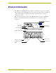
Product Information Product Information The AXB-TC and AXB-TCR Television Controllers are intelligent, microprocessor-controlled systems equipped with a lithium battery to protect stored memory. The television controllers can control a variety of Infrared-controlled devices such as televisions, audio receivers, and videocassette recorders. FIG. 1 shows the front and rear panels of the AXB-TCR.
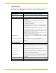
Product Information Specifications The following table list the product specifications for the television controllers. Other than the IR Input Window (on the AXB-TCR only), the specifications for the TC and TCR are identical. AXB-TC/TCR Specifications Dimensions (HWD): (with connectors) Power consumption: • 1.29" x 3.33" x 5.54" (32.8 mm x 84.6 mm x 140.
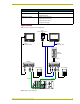
Product Information AXB-TC/TCR Specifications (Cont.) Mounting options: Flat surface Included accessories: • CC-IR TV Sensor (CC-XPS sensor) • CC-IRC IR Emitter Optional accessories: • SE-TC Security Enclosure • PCS Power Current Sensor • VSS2 Video Sync Sensor • 12 VDC Power supply Applications FIG. 2 shows a sample system configuration.
Product Information 4 AXB-TC and AXB-TCR Television Controllers
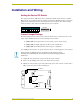
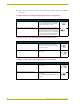
Installation and Wiring Installation and Wiring Setting the Device DIP Switch The eight-position Device DIP switch sets the identification number for the television controller. Make sure the device number matches the number assigned in the AXCESS software program. The quick reference table below shows the switch positions and their numeric value. In the example below, the numeric value of the Device DIP switch is 97 (1+32+64=97).
Installation and Wiring 4. Replace the top portion of the enclosure on the bottom portion. Then, refasten the two Phillipshead screws. JI jumper settings: TV power sensing/TV power current sensing mode JI Jumper Settings: TV Power Sensing/TV Power Current Sensing Television Power (on or off) Sensing mode To use this mode, connect a CC-IRC to the television to detect horizontal scan frequencies up to 65 kHz. Place the 2-pin jumper on the JP1 connector pin's 1 and 2.
Installation and Wiring Wiring The TV sensor, IR emitter, AXlink, and 12 VDC power supply connectors are located on the rear panel of the television controller as shown in FIG. 1 on page 1. Do not connect power directly to the television controller. If you are using power from AXlink, disconnect the wiring from the Central Controller before connecting the wiring to the television controller.
Installation and Wiring IR Emitter connections Connect the CC-IRC IR Emitter to the IR Emitter connector, on the rear panel of the television controller (FIG. 5) to transmit IR control signals to the television. CC-IRC Television IR EMITTER connector GND SG FIG. 5 CC-IRC IR Emitter connector wiring diagram Axlink data and power connections Connect the Central Controllers's AXlink connector to the AXlink connector on the rear panel of the television controller for data and 12 VDC power, as shown in FIG.
Installation and Wiring Use the 12 VDC power supply when the distance between the AMX system and television controller exceeds the limits described in the Wiring Guidelines table on page 7. Make sure to connect only the GND wire on the AXlink connector when using a 12 VDC power supply. Do not connect the PWR wire to the AXlink connector's PWR opening.
Installation and Wiring Installation Install the television controller on any flat surface or inside the optional SE-TC Security Enclosure, as described below: 1. Mount the Axcess Central Controller where it will be used. Then, connect the power supply. 2. Route the Axlink power and data cable, CC-IR TV Sensor cable, CC-IRC IR Emitter cable, and 12 VDC power supply from the television to the television controller's location. 3.
Installation and Wiring Television Power Sensor Adjustment After connecting the CC-IR to the television, the power sensing POT, on the rear of the television controller (see FIG. 1 on page 1), may require adjustment to detect the television's power status: Use a Phillips-head screwdriver and flat-blade tool (non-conducting) to adjust the POT screw. 1. Turn the television off. 2. Locate the POT screw on the circuit card and turn it clockwise 20 full turns or until it clicks.
Installation and Wiring 1. Remove the two Phillips-head screws on the bottom of the television controller enclosure. 2. Pull the two enclosure halves apart and set the bottom portion of the enclosure on a flat surface. 3. Locate the POT screw on the circuit card and turn it counterclockwise with a flat-blade tool until it stops. 4. Turn the POT screw clockwise one-eighth turn to increase signal saturation. Then, send an IR control signal to the television.
Installation and Wiring 6. Carefully pry the battery out of its socket and insert the new battery. Write down the next replacement date on a label by adding 5 years to the replacement date; attach it to the bottom of the television controller. 7. Reattach the enclosure and refasten the two screws. 8. Plug all cables back into the television controllers. There is a danger of explosion if you replace the battery incorrectly.
Installation and Wiring 14 AXB-TC and AXB-TCR Television Controllers
Programming Information Programming Information The television controllers are controlled with channel settings, IR functions, and Axcess Send_Commands. You create software programs with the AMX Axcess programming software. Use the programming information in this section with the Axcess Programming Guide to program television controllers. After you create the IRLIB program, download it to the non-volatile (battery protected) memory in the television controller.
Programming Information IR Functions (Standard Order) The following table lists the IR function, in their standard order.
Programming Information Send_Commands Use the Send_Commands listed in the following table to program the Axcess Central Controller and television controller. ! The device number range for the television controller is 1 through 255. ! Refer to the Axcess Programming Language instruction manual for additional programming information. Send_Commands CARON Enables an IR carrier signal after receiving a 'CARON' command. Example: SEND_COMMAND 1,'CARON' Enables the carrier signal for device 1.
Programming Information Send_Commands (Cont.) ?CTON Sends the current on-time pulse string "'CTON',
Programming Information Send_Commands (Cont.) 'PTOF',
Programming Information Send_Commands (Cont.) XCHM Syntax: Changes the IR output pattern for the XCH command. Variable: SEND_COMMAND ,'XCH-' Mode = 0-4 Example: SEND_COMMAND IR_1,'XCH 3' Sets the IR_1 device's extended channel command to mode 3. Mode 0 Example (default): [x] [x] SEND_COMMAND IR_1, 'XCH 3' Transmits the IR code as 3-enter. SEND_COMMAND IR_1, 'XCH 34' Transmits the IR code as 3-4-enter. SEND_COMMAND IR_1, 'XCH 343' Transmits the IR code as 3-4-3-enter.
Programming Information Firmware Upgrades Firmware upgrades allow you to install the latest available operating system for your AXB-TC or AXB-TCR. The firmware reload is required anytime the unit's LEDs all flash at the same rate as the AXlink LED, or if all LEDs are full-on. To accomplish the upgrade, your computer must be connected to the Axcess Master Controller via a serial (RS-232) interface connecting to the AXlink DB-9 programming port input.
Programming Information F2 can be pressed to select all ONLINE PANEL devices and F3 can be pressed to clear all devices. 5. Press F4 to program the selected device(s), the loading status bar in FIG. 14 then appears. 6. Press F5 to refresh the screen. Verify that all selected panels have the correct firmware version. If any devices still indicated the old version, repeat preceding steps 3 through 5 until all panels indicate the correct firmware version. 7.
Programming Information 3. Click Browse to navigate to the directory containing the firmware file(s). Once a directory containing one or more .TSK files is specified, a list of available .TSK files is displayed in the upper table in this dialog. 4. Select the desired .TSK file from the list. 5. Click Query Online Devices to populate the on-line device list. 6. Select the target AXlink device from the list of online devices in the lower table. 7.
032-004-1213 7/03 ©2003 AMX Corporation. All rights reserved. AMX, the AMX logo, the building icon, the home icon, and the light bulb icon are all trademarks of AMX Corporation. AMX reserves the right to alter specifications without notice at any time. *In Canada doing business as Panja Inc. AMX reserves the right to alter specifications without notice at any time.