
Instruction manual


US
6,642,852
B2
unique
time
period
before
transmitting
its
reply
message.
By
Way
of
example,
a
poWer
monitor
unit
14
may
Wait
a
time
equal
to
20
milliseconds
plus
100
milliseconds
times
its
address
number
before
transmitting
the
reply
message.
Using
a
pre-transmit
delay
based
on
the
unit
address
number
in
this
manner
results
in
each
monitor
14
transmitting
its
status
response
in
a
sequential,
predetermined
manner
(starting
With
unit
0 and
ending
With
unit
7) as
illustrated
in
FIG.
12.
This
further
provides an
additional
level
of
error
checking
capability
to
the
receiving
remote
control since
each
monitor
unit
14
has
a
predetermined
time
WindoW
during
Which
the
remote
control
may
expect
to
receive
a
reply
transmission.
Accordingly,
receipt
of
a
message
out
side
of
this
time
WindoW
Would
be
indicative
of
an
error
condition
resulting
in
the
indication
of
an
“unknown”
state
in
the
table
400
for
the
device
associated
With
the
poWer
monitor
unit
14
that
is
late
With
its
transmission.
The
polling
of
the
poWer
monitor
units
14
may
be
initiated
in
response
to
the
user
activating
one
of
the
special
poWer
keys,
one
of
the
macro
keys,
in
response
to
activation
of
a
given
setup
mode,
at
timed
intervals,
etc.
Without
limitation
For
example,
When
the
“All
On”
key
is
activated,
the
remote
control
transmits
the
status
enquiry
message
and
retrieves
the
poWer
status
of
the
devices
from
the
poWer
monitor
units
14
as
described above.
Once
the
table
400
has
been
updated
With
the
status
of
the
devices,
as
illustrated
in
FIG.
7,
the
remote
control
10
performs
processing
to
command
each
device
that
has
been
identi?ed
to
the
remote
control
(i.e.,
setup)
and
Which
has
a
functioning
poWer
monitor
unit
14
(i.e.,
a
poWer
status
monitor
address
Was
setup
in
the
remote
control
and
the
poWer
status
monitor
has
reported
a
current
status)
to
enter
the
“On”
state.
In
this
regard,
the
transmis
sion
of
the
appropriate
command
signals
to
the
appliances
12
(if
necessary)
may
be
performed
in
a
sequential
order
folloWing
the
order
in
Which
the
devices
are
maintained
Within
the
table
400.
Within
this
sequential
order,
if
a
device
mode
has
not
been
setup
by
the
user
(indicated
by
a
“no”
in
the
data
?eld
440
for
that
device)
this
device
mode
Will
be
skipped
during
the
procedure.
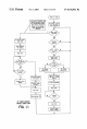
More
speci?cally,
to
initiate
an
“All
On”
procedure,
for
each
device
mode
that
has
been
setup,
it
is
determined
if
a
speci?c
device
supports
explicit
“On”
and
“Off”
commands.
This
is
determined
by
reference
the
command
code
library
for
the
speci?ed
device
using
conventional
look-up
tech
niques.
If
the
device
supports
these
explicit
commands,
the
remote
control
10
merely
transmits
the
explicit
“On”
com
mand
for
that
device
to
place
the
device
in
the
“On”
state
and
the
procedure
continues
With
the
next
device
(if
any).
If
the
device
does
not
support
explicit
commands
(i.e.,
it
supports
a
poWer
toggle
command),
the
current
status
of
the
device
is
retrieved
from
the
poWer
status
?eld
450
of
the
data
table
400.
If
the
status
is
indicated
to
be
“Unknown”
or
“On,”
no
further
processing
for
this
device
is
performed
and
the
procedure
moves
to
the
next
device
(if
any).
If,
hoWever,
the
status
is
indicated
to
be
“Off”
in
the
poWer
status
?eld
450,
the
poWer
toggle
command
for
that
device
is
transmit
ted
for the
purpose
of causing
the
device
to
enter
the
“On”
state.
In
this
manner,
activation
of
the
“All
On”
key
avoids
the
inadvertent
placing
of
a
home
appliance
in
an
unWanted
“Off”
state.
In
a
similar
fashion,
activation
of
the
“All
Of’
key
avoids
the
inadvertent
placing
of
a
home
appliance
in
an
unWanted
“On”
state.
In
this
regard,
activation
of
the
“All
Of’
key
causes
the
transmission
of
an
explicit
“Off”
command,
the
transmission
of
a
poWer
toggle
command,
or
no
action
in
accordance
With
the
logic
set
forth
above
With
respect
to
the
“All
On”
procedure.
10
15
25
35
45
55
65
10
Still
further,
the
table
400
can
be
updated
and
the
data
contained
therein
considered
in
the
performance
of
the
steps
assigned
to
a
programmed Macro
key
or
in
response
to
activation
of
the
single unit
poWer
keys
360.
Again,
a
transmission
of
a status
enquiry
message
and
the
updating
of
the
table
400
can
be
performed
in
response
to
activation
of
these
keys.
The
processing
in
response
to
activation
of
these
keys
Would
be
performed
in
the
same
manner
described
above
With
respect
to
the
“All
On”/“All
Off”
procedures
excepting
that
it
Would
be
performed
on
an
individual
device
basis
as
illustrated
in
FIG.
8.
By
Way
of
speci?c
example,
assuming
a
Macro
key
Was
programmed
to
turn
the
VCR
device
on,
turn
the
TV
device
on,
and
tune
the
TV
device
to
channel
3,
activation
of
the
Macro
key
Would
result
in
the
updating
of
the
table
400
(in
the
manner
described
above)
and
the
processing
of
the
macro
command
steps
as
folloWs
(assuming
the
table
400
indicates
that
the
VCR
and
TV
devices
Were
setup
and
the
addresses
of
their
respective
poWer
monitor
units
Were
also
setup):
For
each
of
the
VCR
and
TV
devices:
It
is
determined
if
the
device
supports
explicit
“On”
and
“Off”
commands.
If
the
device
supports
these
explicit
commands,
the
remote
control
10
merely
transmits
the
explicit
“On”
com
mand
for
the
device
and
the
macro
continues
to
the
next
step.
If
the
device
does
not
support
explicit
commands
(i.e.,
it
supports
a
poWer
toggle
command),
the
current
status
of
the
device
is
retrieved
from
the
poWer
status
?eld
450
of
the
data
table
400.
If
the
status
is
indicated
to
be
“Unknown”
or
“On,”
no
further
processing
for
the
device
is
performed
and
the
macro
moves
to
the
next
step
(if
any).
If,
hoWever,
the
status
is
indicated
to
be
“Off,”
the
poWer
toggle
command
for the
device
is
transmitted
for
the
purpose
of causing
the
device
to
enter
the
“On”
state
and
the
next
step
in
the
macro
chain
is
executed
(if
any).
In
this
manner,
the
remote
control
10
ensures
that
execution of
a
macro
or
the
single
poWer
on
key
Will
not
place
an
appliance
in
an
undesired
state.
While
speci?c
embodiments
of
the
present
invention
have
been
described
in
detail,
it
Will
be
appreciated
by
those
skilled
in
the
art
that
various
modi?cations
and
alternatives
to
those
details
could
be
developed
in
light
of
the
overall
teachings
of
the
disclosure.
For
example,
it
is
contemplated
that
several current
monitor
modules
990
may
be
combined
With
a
single
microprocessor
and
RF
transceiver
980
into a
smart
poWer
strip
900
for
use
in
an
entertainment
center,
as
illustrated
in
FIGS.
13
and
14.
In
this
case,
the
method
of
operation
and
the
processing
logic
is
essentially
the
same
as
described
previously
excepting
that,
in
this
case,
upon
receipt
of
a
poWer
status
query
from
the
remote
control
10
the
microprocessor
66
Will poll
each
poWer
outlet
and
transmit
a
corresponding
number
of
sequential
status
reply
messages
to
the
remote
control
10.
Each
poWer
outlet
in
the
strip
900
can be
assigned
a
unique
address
by
the
user
or
the
user
can
set
one
number
for
the
poWer
strip
Which
causes
the
outlets
to
be
automatically
assigned
sequential
addresses
starting
With
the
user
set
number.
This
approach
alloWs
poWer
strips
900
and
individual
monitor
modules
14
to
be
intermixed
transparently
to
the
remote
control
logic.
Still
further,
it
Will
be
appreciated
that
a
single
poWer
monitor
module
990
could
be
sWitched
betWeen
multiple
poWer
outlets
using
triacs
or
similar
poWer
sWitching
apparatus
under
control
of
the
microprocessor
66.
Accordingly,
it
Will
be
understood
that
the
particular
arrangements
and
proce
dures
disclosed
are
meant
to
be
illustrative
only
and
not