
Instruction manual


US
6,642,852
B2
7
awareness
of
the
current
power
state
(i.e.,
on
or
off)
of
the
one
or
more
home
appliances
12
the
remote
control
10
is
setup
to
control.
The
remote
control
10
may
maintain
the
current
power
state
of
the
home
appliances
12
in
a table
400,
illustrated
in
FIG.
4,
for
further
use
in
a
manner
to
be
described
hereinafter.
As
illustrated
in
FIG.
4,
the
table
400
may
maintain
data
for
each
device
mode
supported
by
the
remote
control
10.
In
the
exemplary
case,
since
the
illus
trated
remote
control
includes
eight
device
mode
keys
330
the
table
400
has
eight
data
?eld
rows
410.
For
each
device
mode
420
data
may
be
maintained
that
is
indicative
of:
1)
an
ID
(430)
assigned
to
the
power
monitor
14
associated
with
the
device
12
to
be
controlled
in
the
given
device
mode;
2)
a
status
of
the
device
setup
(440)
within
the
remote
control
for
the
given
device
mode;
and
3)
a
power
status
(450)
for
the
device
12
as
reported
by
its
associated
power
monitor
unit
14.
More
speci?cally,
the
data
?eld
(430)
maintains
the
unit
address
number
that
corresponds
to
the
user-set
address
of
the
power
monitor
unit
14
associated
with
the
device
to
be
controlled
in
the
given
device
mode.
For
example,
in
the
illustrative
table
of
FIG.
4,
the
remote
control
has
been
setup
to
control
an
appliance
in
the
VCR
device
mode
which
has
been
indicated
to
be
plugged
into a
power
monitor
unit
14
having
an
address
of
“3”
and
to
control
an
appliance
in
the
TV
device
mode
which
has
been
indicated
to
be
plugged
into
a
power
monitor
unit
14
having
an
address
of
“0.”
It
is
to
be
understood
that
not
all
of
the
appliances
12
that
the
remote
control
10
may
control
need
a
power
monitor
unit
14
and,
in
the
case
where
an
appliance
in
a
given
device
mode
is
indicated
to
be
operating
without
a
power
monitor
unit
14,
the
table
400
would
maintain
an
entry
of “none.”
Preferably
the
table
400
is
initialiZed
when
the
remote
control
is
?rst
placed
in
service
such
that
“none”
is
maintained
in
the
data
?eld
430
for
each
device
mode
420
until
such
time
as
the
device
mode
is,
in
fact,
setup
to
indicate
an
address
for a
power
monitor
unit.
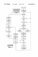
To
set
the
data
in
the
ID
data
?eld
430
for a
device
mode
420,
the
user
may
perform
the
method
generally
illustrated
in
FIG.
5.
By
way
of
eXample,
a
user
might
enter
a
general
setup
mode
(e.g.,
by
activating
the
“Setup”
key
310)
fol
lowed
by
an
indication
to
the
remote
control
that
the
user
speci?cally
desires
to
setup
the
power
module
unit
ID
?eld
of
the
table
400
(e.g.,
by
entering
a
predetermined
key
sequence
using
the
numeric
keys
340,
such
as
“979”).
At
this
time
the
user
may
indicate
to
the
remote
control
10
the
device
mode
of
interest
and
the
ID
number
of
the
power
monitor
unit
associated
with
the
appliance
to
be
controlled
in
the
given
device
mode
(e.g.,
by
hitting
the
appropriate
“Device”
key
330
and
by
hitting
the
numeric
key
340
indicative
of
the
address
of
the
associated
power
monitor
unit).
The
user
could
then
indicate
a
desire
to
eXit
the
setup
mode
(e.g.,
by
again
hitting
the
“Setup”
key
310)
at
which
time
the
indicated
ID
number
would
be
stored
in
the
data
?eld
430
for
the
indicated
device
420.
This
process
can
be
repeated
as
often
as
needed
to
de?ne
the
ID
number
of
the
power
monitor
unit
for
each
device
mode.
This
procedure
may
also
be
timed
to
prevent
the
remote
control
10
from
being
locked
in
a
setup
mode.
By
way
of
an
illustrative
eXample,
to
setup
the
remote
control
such
that
the
table
400
illustrated
in
FIG.
4
results,
the
user
might
hit
the
“Setup”
key,
enter
the
setup
code
“979,”
and
active the
following
keys:
TV-0-AMP-2-VCR-3-CD-1-AUX-4.
The
setup
mode
would
be
eXited
by
again
hitting
the
“Setup”
key.
Further
maintained with
the
table
400
in
data
?eld
440
is
data
indicative
of
whether
an
appliance
to
be
controlled
in
a
given
device
mode
has,
in
fact,
been
setup
by
a
user.
Setup
10
15
25
35
45
55
65
8
in
this
conteXt
is
with
reference
to
the
initial
input
by
the
user
to
identify
the
speci?c
brand/model
of
home
appliance
to
be
controlled
when
the
corresponding
“Device”
button
330
is
activated
(See
for
example
US.
Pat.
Nos.
5,614,906
and
4,959,810).
If
no
device
setup
has
been
performed
for a
given
device
mode
the
data
?eld
440
for
that
device
main
tains
data
indicative
of
this
fact,
e.g.,
it
maintains
data
representative
of
a
state
“No.”
Preferably,
upon
initialiZation
of
the
remote
control
10,
all
of
the
data
?elds
440
are
provided
with
a
default
value
of
“No”
until
such
time
as
the
device
mode
is
setup.
When
a
data
?eld
440
indicates
that
a
device
mode
has
not
been
setup
it
may
be
assumed
that
the
user
does
not
have
a
home
appliance
to
be
controlled
in
this
device
mode
and,
as
such,
this
device
mode
can
be
skipped
during
processing
of an
“All
On”
or
“All Off”
command
which
is
described
hereinafter.
A
still
further
data
?eld
450
within
the
data
table
400
holds
the
current
power
status
(i.e.,
“on”
or
“off”)
of
a
device
as
reported
by
its
associated
power
monitor
unit
14.
If
a
device
is
not
equipped
with
a
power
monitor
unit
14
(i.e.,
the
ID
data
?eld
430
has
data
indicative
of
“none”)
the
data
?eld
450
preferably
maintains
data
indicating
the
appliance
is
in
an
“unknown”
state.
Likewise,
if
communications
with
the
associated
power
monitor
14 have
failed,
the
data
?eld
450
again
maintains
data
indicative
of an
“unknown”
state.
To
poll
the
one
or
more
power
monitor
units
14
to
gather
the
current
power
status,
he
remote
control
10
issues
a
broadcast
status
enquiry
message,
as
illustrated
in
FIG.
6,
via
its
RF
module
40.
The
power
module
units
14
respond
to
the
status
enquiry
message
by
transmitting
a status
response
message
having
data
indicative
of
the
status
of
the
device
associated
with
the
respective
power
monitor
unit
14.
Preferably
the
status
response
messages from
the
one
or
more
power
monitor
units
14
are
transmitted
in
an
orderly
fashion
to
avoid
collisions
at
the
remote
control
10.
Upon
receiving
a status
response
message
from
a
power
monitor
unit
14,
received
via
the
RF
module
40,
the
remote
control
10
strips
the
data
from
the
status
response
message
(i.e.,
the
address
of
the
responding
power
monitor
unit
14
and
the
state
of
the
device
12
associated
with
that
power
monitor
unit
14)
and
updates
the
appropriate
status
data
?eld
450
in
the
data
table
400
to
re?ect
the
received
status
information.
In
the
case
where
no
response
is
received
from
a
power
monitor
unit
14
or
an
invalid/untimely
response
is
received,
the
power
status
of
the
data
?eld
corresponding
to
the
missing
or
failed
power
monitor
unit
14
is
preferably
set
to
“unknown.”
In
responding
to
the
status
enquiry
message
received
at
the
power
monitor
unit
14, the
power
monitor
unit
14
measures
the
power
draw
of
its
associated
home
appliance
as
illustrated
in
FIG.
11.
The
measured
power
draw
is
then
compared
to
the
previously
established
threshold
value.
If
the
measured
power
draw
is
above
the
established
threshold
value,
the
status
of
the
home
appliance
12
is
determined
to
be
“on.”
If,
however,
the
measured
power
draw
is
not
above
the
established
threshold
value,
the
status
of
the
home
appliance
12
is
determined
to
be
“off.”
The
determined
status
is
returned
to
the
remote
control
10
as
data
in
the
status
reply
message.
The
status
reply
message
also
includes
data
that
functions
to
identify
the
power
monitor
unit
14
transmitting
the
status
reply
message.
Pref
erably
this
data
is
the
address
of
the
power
monitor
unit
14
which
the
power
monitor
unit
14
retrieves
by
reading
the
switches
76.
To
prevent
the
collision
of
status
reply
messages
at
the
remote
control
10,
each
power
monitor
unit
14
may
wait an