
Instruction manual


US
6,642,852
B2
5
other
devices
such
as
PDAs,
personal
computers,
or
the
like.
Accordingly,
the
description
that
follows
need
not
be
lim
iting.
As
illustrated,
the
remote
control
10
includes
a
“Setup”
key
310,
a
“PoWer”
key
320,
“Device” keys
330
(for
selecting
the
mode
of
operation—i.e.,
the
home
appliance/
device
to
control),
“Numeric”
keys
340
(corresponding
to
the
digits
0—9),
and
a
group
of
“Macro”
keys
370
to
Which
preprogrammed
or
user
programmable
macros
can be
assigned.
Additional,
optional
keys
may
include
a
pair
of
keys
350
to
command
“All
On”
or
“All Off”
operations
and/or
a
pair
of
keys
360
to
command
“On”
and
“Off”
operations
for a
currently
selected
device.
The
operation
of
the
special
keys
350
and
360,
Which
comprise
a
smart
poWer
feature,
Will
be
described
in
greater
detail
in
the
paragraphs
that
folloW.
The
remaining
keys
illustrated
in
FIG.
3 perform
conventional
remote
control
functions
that
Will
be
Well
understood
by
those
of
ordinary
skill
in
the
art.
For
monitoring
poWer
supplied
to
a
home
appliance
12
and, accordingly,
the
state
of
the
home
appliance
12
(e.g.,
poWered
on
or
off/in
standby
mode),
the
poWer
monitoring
unit
12
includes
a
current
sensing
device
50
as
illustrated
in
FIG.
9.
The
current
sensing
device
50
may
be
in
the
form
of
a
transformer
having
a
primary
Winding
52
Which
is
inserted
in
the
path
of
current
?oW
going
from
the
outlet
16
to
the
home
appliance
12.
In
this
manner,
the
transformer
second
ary
Winding
54
Will
thus
have
a
current
?oW
Which
is
representative
of
the
current
?oW
passing
through
the
trans
former
primary
Winding
52.
In
the
illustrated
current
sensing
device
50,
a
dropping
resistor
56
is
inserted
as a
load
to
covert
the
secondary
Winding
54
current
to
a
voltage.
It
Will
be
appreciated
that
other
current
sensing
devices
50
for
generating
a
signal
representative
of
the
current
being
draWn
by
the
home
appliance
12
may
be used
such
as,
by
Way
of
eXample
only,
any
Hall
Effect
device.
For
conditioning
the
signal
generated
by
the
current
sensing
device
50,
the
poWer
monitor
unit
14
may
also
be
provided With
a
signal
conditioning
circuit
56.
For
eXample,
the
voltage
drop
across
the
resistor
56
can
be
sent
though
a
signal
conditioning
circuit
56
comprised
of
an
ampli?er
recti?er
60/62
and
a
loW-pass
?lter
64.
In
this
manner,
the
AC
voltage
representation
of
the
AC
load
current
can
be
transformed
to
a
DC
voltage
signal
Which
can
be
interfaced
to
a
processor
66
through
an
Analog-Digital
converter
or
Voltage
to
Frequency
Oscillator
(VFO).
Further
eXamples
of
such
circuitry
can
be
seen
in
“analog-digital
CONVER
SION
HANDBOOK,”
Copyright
1972
&
1976
by
Analog
Devices,
Inc.;
Second
Edition,
June,
1976
and
“IC
Op-Amp
Cookbook,”
by
Walter
G.
Jung;
1974, 1980,
and
1986
by
HoWard
W.
Sams
&
Co.,
A
Division
of
Macmillan,
Inc.;
Third
Edition—Fourth
Printing,
1988.
pp.
252
and
253,
Which
are
incorporated
herein
by
reference
in
their
entirety.
The
ampli?er,
recti?er
and
loW
pass
?lter
are
shoWn
in
greater
detail
in
FIG.
10.
For
poWering
the
components
of
the
poWer
monitor
unit
14,
a
voltage
supply
72
is
provided.
By
Way
of
eXample,
the
voltage
supply
72
can
be
circuitry
that
converts
the
AC
voltage
from
the
outlet
16
to
a
voltage
level
that
can
directly
poWer
the
components
of
the
poWer
monitor
unit
14.
Alternatively,
the
voltage
supply
72 can
be
batteries.
Still
further,
the
poWer
monitor
unit
14
may
include
a
small
non-volatile
memory
(such
as
an
EEPROM)
to
maintain
setting
through
poWer
failures,
broWn
outs,
etc.
The
processor
66
has
associated
instructions
for
accepting
the
DC
signal
supplied
from
the
conditioning
circuit
58
and
for
performing
operations
based
on
the
value
of
the
signal.
The
processor
66
also
has
associated
instructions
Which
the
processor
66
uses
in
connection
With an
RF
(or
IR)
module
10
15
25
35
45
55
65
6
to
cause
communications
to
be
transmitted
in
a
format
recogniZed
by
the
remote
control
10.
In
this
regard,
RF
transmissions
can
be
made
using
a
custom-designed
proto
col
operating
in
one
of
the
frequency
bands
allocated
by
national
regulatory
agencies
for
use
in
control
and
status
monitoring,
or
alternatively
by
a
standardiZed
conventional
protocol
such
as
Bluetooth,
etc.,
using
off-the-shelf
compo
nents.
The
construction
and
operation
of
such
RF
transceiv
ers
is
Well
knoW
in
the
art.
Instructions
may
also
be provided
for
alloWing
the
poWer
monitor
unit
14
to
provide
status
information
to
a
consumer by
means
of,
for
eXample,
one
or
more
LEDs
70,
a display,
etc.
Once
the
poWer
monitor
unit
is
initialiZed,
the
poWer
monitor
unit
enters
a
loop
Wherein
it
continually
searches
for
one
of
at
least
tWo
events,
namely,
activation
of
a
user
setup
sWitch
or
receipt
of
a status
enquiry
message
from
the
remote
control
10.
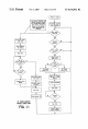
To
con?gure
the
poWer
monitor
unit
14
for
use
in
the
system,
illustrated
in
FIG.
11,
the
poWer
monitor
unit
14
is
set
to
recogniZe
the
“standby/off”
and “on”
load
currents
for
the
home
appliance
12
associated
With
the
poWer
monitor
unit
14.
To
this
end,
a
consumer
Would
place
the
appliance
12
to
be
monitored
in
the
standby
state
and
instruct
the
poWer
monitor
unit
14
to
capture
a
signal
representative
of
the
current
How
of
the
home
appliance
12
in
this
standby
state.
The
instruction
to
capture
a
signal
representative
of
the
standby
current
How
of
the
home
appliance
12
can
be
entered
by
activation
of
a
setup
sWitch
74.
In
response
to
this
instruction,
the
processor
66
monitors
the
DC
voltage
signal
from
the
conditioning
circuitry
58
and
stores
this
voltage
signal
as
the
representation
of
the
standby
current
?oW.
To
setup
the
poWer
monitor
unit
14
to
recogniZe
the
appliance
on
current
?oW,
a
consumer
Would
place
the
appliance
12
to
be
monitored
in
the
on
state
and
instruct
the
poWer
monitor
unit
14
to
capture
a
representation
of
the
resulting
current
?oW.
The
instruction
to
capture
a
repre
sentation
of
the
on
current
How
can be
entered
by, for
eXample,
a
second
activation
of
the
setup
sWitch
74.
In
response
to
this
instruction,
the
processor
66
monitors
the
DC
voltage
signal
from
the
conditioning
circuitry
58 and
stores
this
voltage
signal
as
the
representation
of
the
on
current
?oW.
A
threshold
value
may
then
be
determined
as
the
average
of
the
on
and
off
current
?oW
representation
values.
It
Will
be
appreciated
that
these
setup
procedures
can
be
timed
to
prevent
the
poWer
monitor
unit
14 from
being
locked
in
the
setup
mode
of
operation.
It
Will
be
further
appreciated
that
the
setup
procedure
can
be
performed
by
the
poWer
monitor
unit
prompting
the
user
to
place
the
appli
ance
in
a
given
state
and
automatically
monitoring
the
resulting
current
?oW.
For
use
in
establishing
an
address
for
the
poWer
monitor
unit
14,
Which
address
is
used
to
facilitate
communications
With
the
remote
control
10,
address
setting
device
76
is
provided
and
accessible
by
the
processor
66.
The
address
setting
device
76
may
include
dip
sWitches,
jumpers,
means
for
keying
in
an
address,
or
the
like.
In
the
case
of
dip
sWitches
or
jumpers,
the
address
setting
device
Would
be
used
to
set
a
bit
pattern
that
Would
serve
as
the
address
(e. g.,
three
sWitches
Would
alloW
the
poWer
monitor
14
to
be
set
to
one
of
eight
unique
addresses). Preferably,
the
address
setting
device
76
is
accessible
to
the
consumer
although
the
address
setting
device
can
be
factory
preset.
Additionally,
eXtra
sWitches
76
may
be
provided
in
cases
Where
it
is
desired
to
set
a
unique
system
address
to
alloW
multiple
remote
controllers
10
to
operate
independently
in
the
same
vicinity.
During
the
operation
of
the
system,
the
poWer
monitor
units
14
are
used
to
provide
the
remote
control
10
With