
Instruction manual


US
6,642,852
B2
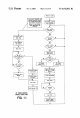
3
FIG.
5
illustrates
an
exemplary
method
for setting
up
the
table
of
FIG.
4
to
enable
the
remote
control
of
the
system
of
FIG.
1
to
receive
poWer
state
information;
FIG.
6
illustrates
an
exemplary
method
for
executing
an
update
of
the
poWer
state
information
table
of
FIG.
4;
FIG.
7
illustrates
an
exemplary
method
for
commanding
multiple
appliances
Within
the
system
of
FIG.
1
to
be
turned
to
the
on
state;
FIG.
8
illustrates
an
exemplary
method
for
commanding
single
appliances
Within
the
system
of
FIG.
1
to
be
turned
to
the
on
state;
FIG.
9
illustrates
a
block
diagram
schematic
of
an
exem
plary
poWer
monitoring
unit
of
the
system
of
FIG.
1;
FIG.
10
illustrates
a
schematic
of an
exemplary
poWer
monitoring
module
of
the
poWer
monitoring
unit
of
FIG.
9;
FIG.
11
illustrates
an
exemplary
method
for setting
up
a
poWer
monitoring
unit
of
FIG.
9
and
for
providing
poWer
state
information
to
the
remote
control
of
the
system
of
FIG.
1;
FIG.
12
illustrates
an
exemplary
transmission
sequence
betWeen
the
poWer
monitoring
units
and
the
remote
control
of
the
system
of
FIG.
1;
FIG.
13
illustrates
a
further
poWer
monitoring
unit
in
the
form
of
a
poWer
strip;
and
FIG.
14
illustrates
a
schematic
diagram
of
the
exemplary
poWer
monitoring
unit
of
FIG.
13.
DETAILED
DESCRIPTION
Turning
noW
to
the
?gures,
Wherein
like
reference
numer
als
refer
to
like
elements,
there
is
illustrated
in
FIG.
1
a
system
for
providing
a
remote
control
With
appliance
poWer
aWareness.
Generally,
the
system
includes
a
remote
control
10
capable of
commanding
the
operation
of
home
appliances
12,
such
as
television
12a and
set-top
box
12b.
It
Will
be
appreciated
that
the
home
appliances
12
can
be
of
different
types
(such
as,
by
Way
of
example
only,
televisions,
VCRs,
DVD
players,
set-top
boxes,
ampli?ers,
CD
players,
game
consoles,
home
lighting,
drapery,
etc.)
manufactured
by
different
manufacturers.
The
home
appliances
12
receive
poWer
from
an
electrical
outlet
16
using
an
intermediate
poWer
monitor
unit
14
having
a
socket
for
receiving
the
plug
of an
appliance
12
and
a
plug
for
insertion
into a
socket
of
the
electrical
outlet 16.
As
Will
be
described
in
greater
detail,
the
poWer
monitor
unit
14
bi-directionally
communicates
With
the
remote
control
10
to
provide
the
remote
control
10
With
aWareness
of
the
poWer
state
of
a
home
appliance
12.
In
this
manner,
the
remote
control
10
can
consider
the
poWer
state
of
the
home
appliances
When
executing
a
macro
or
other
commands.
For
communicating
With
the
consumer
appliances
12
as
Well
as
the
poWer
monitor
units
14, the
remote
control
10
preferably
includes
a
processor
24
coupled
to
a
ROM
memory
26,
a
key
matrix
28
(in
the
form
of
physical
buttons,
a
touch
screen,
or
the
like),
an
internal
clock
and
timer
30,
an
IR
(or
RF)
transmission
circuit
32
(for
sending
signals
to
a
home
appliance
12),
an
RF
(or
IR)
bi-directional
commu
nications
module
40
(for
sending
and
receiving
signals
from
a
poWer
monitor
unit
14), a
non-volatile
read/Write
memory
34,
a visible
LED
36
(to
provide
visual
feedback
to
the
user
of
the
remote
control
20),
and
a
poWer
supply
38
as
illustrated
in
FIG.
2.
As
Will
be
appreciated,
the
transmission
circuit
32
and
communications
module
40
perform
opera
tions
that
could
be
performed
by
a
single
device.
Accordingly,
the
transmission
circuit
32
and
communica
tions
module
40
need
not
be
separate
and
distinct
compo
nents.
10
15
20
25
30
35
40
45
50
55
60
65
4
The
ROM
memory
26
includes
executable
instructions
that
are
intended
to
be
executed
by
the
processor
24
to
control
the
operation
of
the
remote
control
10.
In
this
manner,
the
processor
24
may
be
programmed
to
control
the
various
electronic
components
Within
the
remote
control
10,
e.g.,
to
monitor
the
poWer
supply
38,
to
cause
the
transmis
sion
of
signals,
etc.
MeanWhile,
the
non-volatile
read/Write
memory
34,
for
example
an
EEPROM,
battery-backed
up
RAM,
Smart
Card,
memory
stick,
or
the
like,
is
provided
to
store
user
entered
setup
data
and
parameters
as
necessary.
While
the
memory
26
is
illustrated
and
described
as
a
ROM
memory,
memory
26
can
be
comprised
of
any
type
of
readable
media,
such
as
ROM,
RAM,
SRAM,
FLASH,
EEPROM,
or
the
like.
Preferably,
the
memory
26
is
non
volatile
or
battery-backed
such
that
data
is
not
required
to
be
reloaded
after
battery
changes.
In
addition, the
memories
26
and
34
may
take
the
form
of
a
chip,
a
hard
disk, a
magnetic
disk,
and/or
an
optical
disk.
For
commanding
the
operation
of
home
appliances
of
different
makes,
models,
and
types, the
memory
26
also
includes
a
command
code
library.
The
command
code
library
is
comprised
of
a plurality
of
command
codes
that
may
be
transmitted
from
the
remote
control
10
for
the
purpose
of
controlling
the
operation
of
the
home
appliances
12.
The
memory
26
also
includes
instructions
Which
the
processor
24
uses
in
connection
With
the
transmission
circuit
32
to
cause
the
command
codes
to
be
transmitted
in
a
format
recogniZed
by
the
target
home
appliance
12.
Similarly,
the
memory
26
also
includes
instructions
Which
the
processor
24
uses
in
connection
With
the
communications
module
40
to
cause
communications
to
be
transmitted
in
a
format
recogniZed
by
the
poWer
monitor
units
14.
To
identify
home
appliances
12
by
type
and
make
(and
sometimes
model)
such
that
the
remote
control
10
is
adapted
to
transmit
recogniZable
command
codes
in
the
format
appropriate
for
such
identi?ed
home
appliances
12,
data
may
be
entered
into
the
remote
control
10.
Since
methods
for setting
up
a
remote
control
to
control
the
operation
of
speci?c
home
appliances
is
Well-knoWn,
it
Will
not
be
described
in
greater
detail
herein.
Nevertheless,
for
addi
tional
information
pertaining
to
remote
control
setup,
the
reader
may
turn
to
US.
Pat.
Nos.
5,614,906
and
4,959,810
Which
are
incorporated
herein
by
reference
in
their
entirety.
To
cause
the
remote
control
10
to
perform
an
action,
the
remote
control
10
is
adapted
to
be
responsive
to
events,
such
as
a
sensed
user
interaction
With
one
or
more
keys
on
the
key
matrix
28.
More
speci?cally,
in
response
to
an event
appro
priate
instructions
Within
the
memory
26
are
executed.
For
example,
When
a
command
key
is
activated
on
the
remote
control
10,
the
remote
control
10
may
read
the
command
code
corresponding
to
the
activated
command
key
from
memory
26
and
transmit
the
command
code
to
a
home
appliance
12
in
a
format
recogniZable
by
the
home
appliance
12.
It
Will
be
appreciated
that
the
instructions
Within
the
memory
26
can
be
used
not
only
to
cause
the
transmission
of
command
codes
to
home
appliances
12
but
also
to
perform
local
operations.
While
not
limiting,
local
opera
tions
that
may
be
performed
by
the
remote
control
10
include
favorite
channel
setup,
macro
button
setup,
com
mand
function
key
relocation,
etc.
Since
examples
of
local
operations
can
be
found
in
US.
Pat.
Nos.
5,481,256,
5,959,
751,
6,014,092,
Which
are
incorporated
herein
by
reference
in
their
entirety,
they
Will
not
be
discussed
in
greater
detail
herein.
By
Way
of
further
example,
an
exemplary
remote
control
10
is
illustrated
in
FIG.
3.
While
illustrated
as a
conventional
hand-held
remote
control,
the
remote
control
can
include