
Installation guide


For full warranty information, refer to the AMX Instruction Manual(s) associated with your Product(s).
5/12
©2012 AMX. All rights reserved. AMX and the AMX logo are registered trademarks of AMX.
AMX reserves the right to alter specifications without notice at any time.
3000 RESEARCH DRIVE, RICHARDSON, TX 75082 • 800.222.0193 • fax 469.624.7153 • technical support 800.932.6993 • www.amx.com
93-5774-01 REV: A
Checking The Installation
After set-up is complete:
1. Check continuity of relay wiring.
2. Check cable numbers and wiring, interfaces and sources against supplied
documentation.
3. Install tab strips to jumper between shared commons and clip off excess tabs.
4. Insert relay wiring terminals into AXB-REL8.
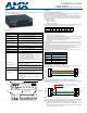
Relay connections
The relay specification is 1 A @ VAC or VDC. FIG. 5 shows the relay wiring diagram for the
AXB-REL8. The dotted lines are used to indicate commons. Install supplied tab strips to
jumper between shared commons. Clip off excess tabs and bend strip up, away from other
wiring.
Testing The Installation
1. Check AxLink status LED - it should blink once per second (see Specifications table for
AxLink status LED).
2. Relay LED lights, but source does not activate:
3. Check wiring continuity.
4. Check jumpers used for shared commons.
5. Check cable and source against supplied documentation.
6. Check operational status of interface or source.
Rack-Mounting the AXB-REL8 (optional)
To rack-mount the AXB-REL8 into the optional AC-RK Accessory Rack Kit:
1. Remove any connected relay and AxLink connectors from the rear panel.
2. Remove the two screws on the front panel of the AXB-REL8.
3. Remove the front panel and the space bracket behind the panel.
4. Place the unit in the appropriate opening in the AC-RK.
5. Place the front panel of the AXB-REL8 on the front of the rack, over the unit.
6. Fasten the front panel to the rack and to the unit with the two screws you removed.
System Worksheet
FIG. 5 Relay wiring diagram
4
3
2
1
B
B
A
A
B
A
B
A
6
5
B
A
B
A
8
7
B
A
B
A
RELAYS SHARING A COMMON
Jumper "A" pins with tab strip
RELAYS WITH DISCRETE COMMONS
Wire commons individually
FIG. 6 AXB-REL8 System Worksheet