
User Guide


Installation
20
AXB-PT15 PosiTrack Camera Controller
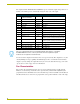
Using the RS-232 DB-9 connector
The RS-232 DB-9 (male) connector on the PosiTrack units connect to the camera head’s RS-232
connector. The following table shows the (DB-9) RS-232 connector wiring diagram.
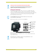
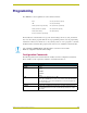
Preparing the PosiTrack Controllers for communication
The AXlink Device DIP switch is located beneath the round cover on the back of the PT15.
Set these switches to the desired device value based on the number of PosiTrack units being used in
a particular system. The initial unit is defaulted with a device number of #90. Any additional units
must have values that do not conflict with other PosiTrack units being used. Refer to the Setting the
AXlink Device DIP switch (S5) section on page 8 for more information.
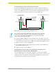
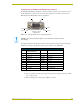
FIG. 19 External RS-232 control device or PC wiring diagram
External RS-232
DB-9 connector
(female)
PWR (+)
GND (-)
Local +12 VDC
(coming from
To the PosiTrack
AXlink/PWR connector
power supply
an external
power supply)
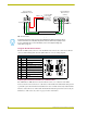
Side view
Top view
(3) AXP/TX
(2) AXM/RX
(5) GND -
AXP/TX
AXM/RX
GND -
For RS232 stand-alone mode, the 8-position AXlink Device DIP switch (S5) positions
1 thru 8 must all be set to Off (all down) and the internal communication jumpers must
be set to RS232 mode. For more information, refer to the Jumper Settings (top
view) table on page 10.
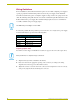
(DB-9) RS-232 Connector Pinouts
Pin Signal Function
1 N/A Not used
2 RXD Receive data
3 TXD Transmit data
4 DTR Data terminal ready (not used)
5 GND Signal ground
6 DSR Data set ready (not used)
7 RTS Request to send (not used)
8 CTS Clear to send (not used)
9 N/A Not used
9
8
7
6
5
4
3
2
1
9
8
7
6
Female
Male