
User Guide


Installation
19
AXB-PT15 PosiTrack Camera Controller
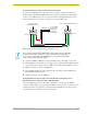
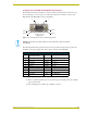
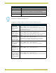
Using the AXlink connector for data with external power
To use the 4-pin AXlink (female) captive-wire connector for data communication and power
transfer, the incoming PWR and GND cable from the 12 VDC-compliant power supply must be
connected to the AXlink cable connector going to the PosiTrack Controller. FIG. 18 shows the
wiring diagram. Always use a local power supply to power the PosiTrack unit.
1. Unscrew the PWR and GND wires on the terminal end of the power supply’s 2-pin cable.
2. Pair the GND wires from both the power supply and the Central Controller AXlink connectors
and insert them into the clamp position for GND on the PosiTrack unit’s AXlink connector.
3. Tighten the clamp to secure the two GND wires.
4. Place the PWR wire from the power supply into the open clamp position for PWR on the
PosiTrack unit’s AXlink connector.
5. Tighten the clamp to secure the PWR wire.
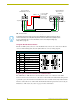
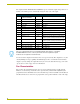
Using the AXlink connector with an external RS-232 control device or PC
This method is for use with a Stand-alone AXB-PT15 Only.
To use the AXlink 4-pin connector with a PC or other RS-232 controller, wire the AXlink
connector to a DB-9 female connector, as shown in FIG. 19. Connector pins 2, 3, and 5 are used for
data and ground. For some applications requiring hardware handshaking, it may be necessary to
strap pins 7 (request to send) and 8 (clear to send) together.
FIG. 18 AXlink connector wiring diagram (using external power source)
PWR (+)
GND (-)
Local +12 VDC
(coming from
To the PosiTrack
To the external Central Controller
AXlink/PWR connector
power supply
an external
power supply)
Top view
Top view
AXP/TX
AXM/RX
GND -
AXP/TX
AXM/RX
GND -
Do not connect the wire from the PWR terminal on the Central Controller to the PWR
terminal on the PosiTrack unit when you connect an external power supply. Make
sure to connect only the AXM, AXP, and GND wires on the PosiTrack unit’s Axlink
connector when using a local power supply.