
User Guide


Pre-Installation
11
AXB-PT15 PosiTrack Camera Controller
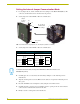
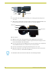
9. Using the 1/16” Allen wrench, insert the four BHSC screws, located around the connector
panel.
10. Use the wire tie-mount to secure connector cables.
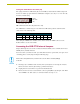
Configuring An External Camera/Lens Power Supply
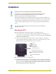
The camera/lens power switch, located between the AXlink and DB-15 connectors, regulates the
power to the camera/lens from the PosiTrack unit (see FIG. 6).
The power switch opens (turns Off) or closes (turns On) the circuit feeding power to the camera/
lens assembly. Refer to the Wiring the Connectors section on page 17 for more information about
the control panel.
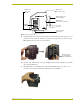
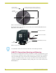
Flip the Lens Power switch to the left if you are only providing power to the camera/lens
assembly through the PosiTrack unit.
Flip the Lens Power switch to the right if you are providing external power to the camera/
lens assembly. By turning the switch Off, the dedicated +12 VDC stops providing
additional power to the camera/lens; preventing damage to power supplies and noise in
the video cables.