
User Guide


Pre-Installation
8
AXB-PT15 PosiTrack Camera Controller
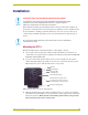
Setting the AXlink Device DIP switch (S5)
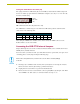
The eight-position Device DIP switch (S5), shown in FIG. 5, must match the number assigned in
the Axcess software program. The Device DIP switch example is set to 90 (2 + 8 + 16 + 64 = 90),
the factory default setting.
The AXlink device number range is 1-255. The Device DIP switch positions determines their
values, based on the following table:
After setting the AXlink device number, remove and reconnect the AXlink connector on the
PosiTrack unit to save the new number.
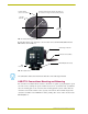
Accessing the AXB-PT15 Internal Jumpers
Jumpers J6 through J8, located on the circuit board inside the PT15, set the communication mode to
AXlink (factory default) or RS-232.
You need a 5/64” (1.98 mm) and 1/16” (1.59 mm) Allen wrench to open the unit, and a pair of non-
conducting pliers to set the jumpers using the following steps.
1. Discharge any accumulated static electricity from your body before removing the enclosure.
Remove the static electricity by touching a grounded metal object.
2. Unplug all connectors from the rear panel of the PosiTrack unit.
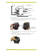
3. Remove the four screws, located around the connector panel (FIG. 6), by using the 1/16” Allen
wrench. BHSC is the abbreviation for the Button Head Socket Cap screws.
FIG. 5 AXlink device DIP switch (S5) (default value of 90)
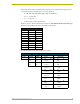
Device DIP Switch (S5) Settings and Values
Position 12 34567 8
Value 1 2 4 8 16 32 64 128
AXlink
DIP switch
(S5)
1 2 3 4 5 6 7 8
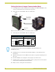
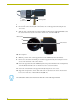
Remove the control panel before you remove the cover, in order to avoid any damage
to the unit.