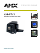
instruction manual AXB-PT15 PosiTrack Camera Controller C a m e ra C o n t r o l l e r s
AMX Limited Warranty and Disclaimer AMX Corporation warrants its products to be free of defects in material and workmanship under normal use for three (3) years from the date of purchase from AMX Corporation, with the following exceptions: • Electroluminescent and LCD Control Panels are warranted for three (3) years, except for the display and touch overlay components that are warranted for a period of one (1) year.
Table of Contents Table of Contents Introduction ...............................................................................................................1 Specifications .................................................................................................................... 2 Lens Control Modes .......................................................................................................... 3 Servomotor Mode........................................................................
Table of Contents Programming .......................................................................................................... 25 Configuration Commands ............................................................................................... 25 Channel Commands ....................................................................................................... 33 Pan/tilt functions...........................................................................................................
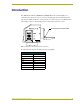
Introduction Introduction The AXB-PT15 PosiTrack 15 (FG630-63 and FG630-64) Camera Controller (FIG. 1) is a camera/lens controllers used for precise camera-positioning applications. This PosiTrack unit supports both AXlink and RS-232 control protocols and connects directly to an AXlink network. All controllers contain on-board intelligence for consistent motion and lens control. Dual Camera/Lens Cradle Assembly FIG.
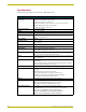
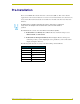
Introduction Specifications The following table lists the specifications for all PosiTrack units. Specifications Dimensions (HWD): AXB-PT15 • Camera controller: 6.43" x 5.61" x 5.38" (16.32 cm x 14.25 cm x 13.67 cm) • Camera mount: 0.65" x 2.26" x 3.23" (1.75 cm x 5.74 cm x 8.21 cm) • Cradle support bracket: 3.64" x 5.50" x 0.20" (9.25 cm x 13.97 cm x 0.51 cm) Power Consumption: • 4 A max @ 12 VDC Weight: • 10.51 lbs. (4.
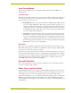
Introduction Lens Control Modes The Servomotor and Motor modes are two Analog Voltage Control methods available on the PosiTrack units. Servomotor Mode This method is generally used in broadcast or videoconference-style lenses. The voltage range used for servomotor style lenses is +2.5 to +7.5 VDC. These lenses can be controlled in two different modes: positional mode and speed mode. Positional mode is the most common Servomotor mode.
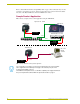
Introduction Refer to the PosiTrack Unit Lens Compatibility table on page 1. Four solid state relays are also provided to control the zoom, focus, and iris speed/position mode selection and iris local/auto selection on the Fujinon MD series and Canon KTSA series lenses. Sample Product Application FIG. 2 shows a sample camera control application using the AXB-PT15.
Pre-Installation Pre-Installation There are four SPDT slide switches in the lens control section (FIG. 3). Three of the switches toggle the lens control selection between servomotor or motor mode hardware for control of zoom, focus, and iris. The fourth selects between ± 6 VDC and ± 12 VDC control for motor mode lens functions. An SPDT switch is a Single Pole-Double Throw switch. This switch is completed at both positions. An example is the Volt switch that is active in both the 6 and 12 positions.
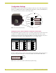
Pre-Installation Configuration Settings Ther PosiTrack 15 unit contains switches for setting the control mode, lens control voltage, RS-232 baud rate, and AXlink address. Before installing the PosiTrack unit, you must set the DIP switches, lens control mode switches, and lens control voltage switch. AXlink LED S6 VOLT 6 12 S M S M S M RS-232 S1 ZOOM S3 FOCUS S4 IRIS AXlink FIG.
Pre-Installation The PosiTrack unit contains one EIA RS-232C standard port for equipment that requires RS-232 control. The following communication protocols are supported: 300, 600, 1200, 2400, 4800, 9600, 19200, and 38400 baud 7, 8, or 9 Data bits 1 or 2 Stop bits Even, Odd, and None parity settings The RS-232 factory default communications settings are: 9600 baud, No Parity, 8 bits, and 1 stop bit. The following table lists the RS-232 Port DB-9 (male) pinouts.
Pre-Installation Setting the AXlink Device DIP switch (S5) The eight-position Device DIP switch (S5), shown in FIG. 5, must match the number assigned in the Axcess software program. The Device DIP switch example is set to 90 (2 + 8 + 16 + 64 = 90), the factory default setting. AXlink DIP switch (S5) 1 2 3 4 5 6 7 8 FIG. 5 AXlink device DIP switch (S5) (default value of 90) The AXlink device number range is 1-255.
Pre-Installation BHSC screws (two screws in rear) BHSC screws (two screws on top) Tilt-head screws (four screws available) RS-232 BHSC screws (five screws on each side) LENS Power Switch LENS POWER AMX CAM AXlink Connector panel (four screws) FIG. 6 Pan-head screw locations 4. Carefully pull the connector panel away from the main unit until the bottom edge of the cover clears the connector panel. Be careful not to damage the pins attached to the connector panel. FIG.
Pre-Installation Setting the Internal Jumper Communication Mode 1. Locate jumpers J6, J7, and J8 communication mode jumpers on the Mother PCB (FIG. 9). The connectors and the main board are mounted onto the pan base. 2. Set the jumpers for either AXlink or RS-232 communication. Jumper locations (3 pair) J8 J6 J6, J7, and J8 communication mode settings Lens control section FIG. 9 Communication mode jumpers J6, J7, and J8 (factory default set to AXlink) 3.
Pre-Installation 9. Using the 1/16” Allen wrench, insert the four BHSC screws, located around the connector panel. 10. Use the wire tie-mount to secure connector cables. Configuring An External Camera/Lens Power Supply The camera/lens power switch, located between the AXlink and DB-15 connectors, regulates the power to the camera/lens from the PosiTrack unit (see FIG. 6). The power switch opens (turns Off) or closes (turns On) the circuit feeding power to the camera/ lens assembly.
Pre-Installation 12 AXB-PT15 PosiTrack Camera Controller
Installation Installation IMPORTANT! READ THIS DOCUMENT BEFORE MOUNTING CAMERA. Proper balance of the camera mount (with camera/lens/cradle) will result in optimal performance. Follow these balancing instructions prior to operation. Failure to balance the camera mount can result in poor performance. This PosiTrack unit enables pan and tilt functionality for mounted camera/lens assemblies and provides lens control functions for teleconferencing lenses.
Installation Position marker (on the outer surface) Camera points this way when the pan drive is in the center of its range of motion (Home position) Ø 3.453" 87.7 mm 3.00 BHC” 76.20 mm 3.45" (87.7mm) FIG. 11 Tilt Hub (Mounting plate) dimensions Each PosiTrack unit can be mounted to camera mounts such as the TM-CAM, WM-CAM, and PM-CAM as shown in FIG. 12. Cradle support bracket Camera mount assembly PM-CAM (Pedestal mount) Wire tie-mount FIG.
Installation 0.750" 19.05 mm 0.750" 0.00" 19.05 mm Position markers 0.750" 19.05 mm 0.250" 6.35 mm Camera points in this direction 0.00" 0.250" 6.35 mm 0.750" 19.05 mm 0.56" 39.62 mm FIG. 13 Tilt Hub dimensions for the PT15 unit Do not lift the PosiTrack unit by the Camera/Lens cradle as this procedure could damage internal components. To mount and balance the camera/lens: 1.
Installation cradle (bottom view) balancing beam FIG. 15 Balancing the camera/lens cradle assembly 6. Re-attach the camera mount (with camera/lens) to the cradle support bracket using the two 1/2” screws. 7. Take the entire camera/mount and cradle assembly and align the lens with the Tilt Hub so that the vertical-axis intersects the center of the camera’s iris, as shown in FIG. 16. Marker points Iris Vertical tilt-axis FIG. 16 Iris alignment with vertical tilt-axis 8.
Installation IMPORTANT! READ THIS DOCUMENT BEFORE MOUNTING CAMERA. Proper balance of the camera mount (with camera/lens/cradle) will result in optimal performance. Follow these balancing instructions prior to operation. Failure to balance the camera mount can result in poor performance. Wiring the Connectors The PosiTrack Controller has an RS-232 DB-9 connector, lens control DB-15 high-density connector, and an AXlink 4-pin connector.
Installation Wiring Guidelines In most installations, the PosiTrack Controllers require a local 12 VDC-compliant power supply to operate properly. The maximum wiring distance between the power supply and the PosiTrack Controller is determined by power consumption, supplied voltage, and the wire gauge used for the cable. The following wiring table lists wire sizes and the maximum lengths allowable between the PosiTrack unit and the power supply. The maximum wiring lengths are based on a minimum of 13.
Installation Using the AXlink connector for data with external power To use the 4-pin AXlink (female) captive-wire connector for data communication and power transfer, the incoming PWR and GND cable from the 12 VDC-compliant power supply must be connected to the AXlink cable connector going to the PosiTrack Controller. FIG. 18 shows the wiring diagram. Always use a local power supply to power the PosiTrack unit.
Installation To the PosiTrack AXlink/PWR connector External RS-232 DB-9 connector (female) Local +12 VDC power supply (coming from an external power supply) PWR (+) GND (-) (3) AXP/TX Side view (2) AXM/RX (5) GND - AXM/RX AXP/TX GND - Top view FIG. 19 External RS-232 control device or PC wiring diagram For RS232 stand-alone mode, the 8-position AXlink Device DIP switch (S5) positions 1 thru 8 must all be set to Off (all down) and the internal communication jumpers must be set to RS232 mode.
Installation Using the lens control DB-15 HD (high density) connector The PosiTrack Controller is designed to control servomotor and motor mode camera lenses. See the Pre-Installation section on page 5 to set the lens switches for servomotor or motor mode. FIG. 20 shows the DB-15 HD connector pin numbers. Pin 5 Pin 1 Pin 6 Pin 10 Lens control DB-15 HD (female) connector wiring pinouts Pin 15 Pin 11 FIG.
Installation The outputs use Pulse Width Modulation (PWM) for speed control. The output voltage values are ± 6 VDC or ±12 VDC. Speed is controlled by varying the duty cycle of the output.
Installation Setting the adjustable pan-limit stops The Central Controller should be programmed by an AMX Axcess programmer before beginning. Refer to the Specifications section on page 2 for more information on programming devices. To set the adjustable pan-limit stops: 1. Ensure that there is enough slack in the lens, camera, and PosiTrack units’ AXlink cables to accommodate the full range of pan motion. 2.
Installation 24 AXB-PT15 PosiTrack Camera Controller
Programming Programming The AXB-PT15 control capabilities for camera functions include: • Pan • Focus (servomotor; speed) • Tilt • Focus (motor drive) • Zoom (servomotor; positional) • Iris (servomotor; positional) • Zoom (servomotor; speed) • Iris (servomotor; speed) • Zoom (motor drive) • Iris (motor drive) • Focus (servomotor; positional) The PosiTrack is controlled with device-specific channel settings and Axcess Send_Commands.
Programming Variables for the Configuration Commands (Cont.) Parameters Description Speed 0 to 127; where 0 is the slowest and 127 is the fastest (default). Deviation 0 to 127; where 0 is most accurate but can have some jitter. Default is 2, meaning the position can be within + 2 from the specified position. Distance 0 to 127; distance from the specified position. Ramp Time 1 to 255; time in 10ms increments it takes the motor drives to ramp up to speed.
Programming Configuration Commands (Cont.) CLEAR HOME Clears the current home position and goes to the default setting and clears presets. CLEAR LIMIT ALL Clears all of the limits. CLEAR LIMIT DOWN Clears the tilt-down limit. CLEAR LIMIT LEFT Clears the pan-left limit. CLEAR LIMIT RIGHT Clears the pan-right limit. CLEAR LIMIT UP Clears the tilt-up limit. CURRENT SPEED PRIORITY=CHANNEL Changes the operational mode of channels 31, 32, 35, and 36.
Programming Configuration Commands (Cont.) FOCUS PRESET=SPEED This is applicable only if the FOCUS SIGNAL=S command is in effect, and the FOCUS switch is set to the S position (servomotor mode). Sets the FOCUS voltage output to recall speed presets. Syntax: SEND_COMMAND CAM,"’FOCUS PRESET=SPEED’" The command for FOCUS output to servomotor mode or motor mode MUST be configured to match the switch settings.
Programming Configuration Commands (Cont.) GET VERSION (version 3.00 or higher) Displays the current firmware version (Boot and Download) on the terminal. The Boot version sent back is determined by checking the version in flash memory. Syntax: SEND_COMMAND CAM,"’GET VERSION’" This command is issued from Terminal Emulator mode. When using a NetLinx master, the ’MSG ON’ command must first be issued to see the status.
Programming Configuration Commands (Cont.) IRIS SIGNAL=S This setting corresponds to the S position (servomotor mode) setting on the IRIS switch. Sets the Iris output to be a servomotor output. Syntax: SEND_COMMAND CAM,"’IRIS SIGNAL=S’" The command for IRIS output to servomotor mode or motor mode MUST be configured to match the switch settings. IS Sets the lens’ Iris mode to speed. Syntax: SEND_COMMAND CAM,"’IS’" This command can be used only for servomotor mode.
Programming Configuration Commands (Cont.) READ ALL Forces the device to read and update levels to the Central Controller. Syntax: SEND_COMMAND CAM,"’READ ALL’" RUN TESTS Runs and checks error values 244 and 245 to see if the gears are properly aligned to their respective grooves. Syntax: SEND_COMMAND CAM,"’RUN TESTS’" Refer to the Diagnostic error values section on page 39 for more detailed information.
Programming Configuration Commands (Cont.) ZAP! Syntax: Initializes all memory in SEND_COMMAND CAM,"’ZAP!’" the unit. This includes speed settings, deviation settings, configuration settings, and all presets. Warning! This command clears all user-defined settings. ZOOM PRESET=POS Sets the Zoom voltage output to recall positional presets (default).
Programming Channel Commands Use channel commands to program pan/tilt, servomotor positional, servomotor speed, and motor mode functions.
Programming Motor mode lens functions Motor Mode Lens Functions Channel State Function 1 On Iris (+) at current speed 3 On Zoom (+) at current speed (increases output voltage) 4 On Focus (+) at current speed 5 On Iris (-) at current speed 7 On Zoom (-) at current speed (decreases output voltage) 8 On Focus (-) at current speed 10 On Iris (+) at maximum speed 12 On Zoom (+) at maximum speed (output minimum voltage) 13 On Focus (+) at maximum speed 14 On Iris (-) at maximum sp
Programming Status Channels Channel State Function 29 On Unit is panning 30 On Unit is tilting 95 On Unit has found its max pan left limit 96 On Unit has found its max pan right limit 97 On Unit has found its max tilt up limit 98 On Unit has found its max tilt down limit 228 On Unit has found its HOME position 248 On Unit is finding HOME position The following is an example of how to use the above functions to obtain a visual status of the movement of the PosiTrack without being
Programming Levels The following table lists the Axcess/NetLinx levels.
Programming Parameters - Send_Commands (Cont.) Parameters Description Time (optional) If specified, 0 to 255 in tenths of a seconds; if not specified, at current rate. Position 0 to 255; value of POT input. Corresponds to a position of the unit. 0 is one end of the POT and 255 is the other end. Not directly related to an output level voltage. 0 to 65535 when using the 'AD MODE x 10' command, or for pan/ tilt commands. Corresponds to a position of the unit.
Programming Positional Commands (Cont.) GL This command can be used for all modes. Turns on the specified output at the current speed until the specified position (as read by the Pan or Tilt encoder) is reached. Syntax: "’G
Programming Positional Commands (Cont.) PR This command can be used for servomotor positional mode applications. Syntax: Sets the ramp rate of the specified output "’P
Programming Error Values and Descriptions Error Description 230 Shows there is an error on the system. This value always appears in conjunction with another number. It acts as a precursor to any other error messages, as an announcement that an error has been found and the following values are the errors found. 240 Shows that there is a problem with the Pan Encoder on the PosiTrack. The encoder is a device that counts the revolutions of the pan motor.
Programming The following table lists preset commands. Preset Commands CANCEL PRESET Immediately stops any active preset recall in motion. CP Clears a preset from memory. Examples: SEND_COMMAND CAM, "’CANCEL PRESET’" Syntax: "’CP’" Variables: preset = 1 - 255 Examples: SEND_COMMAND CAM, "’CP1’" Clears Preset 1. SEND_COMMAND CAM, "’CP100’" Clears Preset 100. RP Recalls a stored preset.
Programming Preset Commands (Cont.) SEND_COMMAND CAM,"’RP10S64’" Recalls preset 10. If any are in positional mode, the current voltages for zoom, focus, and/or iris will be ramped to the preset voltages at the current speed. If any are in speed mode, the motor drive outputs for zoom and/or focus will move at half speed (64). Pan/tilt outputs will move at half speed. Turns on channel 110 when preset 10 is reached. SEND_COMMAND CAM,"’RP10T100S64’" Recalls preset 10.
Programming RS-232 Commands (Cont.) CTSPSH Enables pushes, releases, and status information on channel 255 for CTS hardware handshake input. HSOFF Disables hardware handshaking (default). Syntax: "’CTSPSH’" If CTS is high, channel 255 is On. Example: SEND_COMMAND CAM,"’CTSPSH’" Syntax: "’HSOFF’" Example: SEND_COMMAND CAM,"’HSOFF’" HSON Syntax: Enables hardware handshaking.
Programming RS-232 Send_Strings PosiTracks have special Send_String escape sequences. If any of the three-character combinations listed below are found anywhere within a Send_String program instruction, they are treated as a command and not the literal characters. RS-232 Send_Strings "'27,18,0'" Clears the ninth data bit to 0 for all subsequent characters to be transmitted. It is used in conjunction with the 'B9MON' command.
Programming General Format (Cont.) Byte No. Type Range Direction 4 Pan Feedback 0-65535 From PT 5 Tilt Feedback 0-65535 From PT 6 Zoom Pot Feedback 0-65535 From PT 7 Focus Pot Feedback 0-65535 From PT RS-232 Levels that are valid are 0-7. The following table lists the request functions sent to PosiTrack unit.
Programming Response mask Data is automatically sent if the PosiTrack unit receives a change request. The response mask should be disabled if the change request data is not used. Bits in the response mask (the Return/Respond Strings from the PosiTrack Units table) turn data off.
Upgrading the Firmware Upgrading the Firmware This section outlines the steps necessary to setup a valid connection to a target Axcess Master and then update the on-board firmware. Before beginning: 1. Setup and configure your target Axcess Master. 2. Verify that the Master is receiving power and is turned On. 3. Verify that you have the latest NetLinx Studio installed on your PC. 4. If an update is necessary, download the latest Studio software by first logging in to www.amx.
Upgrading the Firmware 3. Click the Communications Settings button to open the Communications Settings dialog (FIG. 22). 4. Click the Axcess Master radio button (from the Platform Selection section) to indicate you are working with a Axcess Central Controller/Master (such as the AXCENT or AXCENT 3 PRO). 5. Click the Serial radio button (from the Transport Connection Option section) to indicate you are connecting to the Master via a (Serial) COM port. 6.
Upgrading the Firmware Target Axcess Master Detected Axcess Devices FIG. 23 Sample Workspace window (showing the OnLine Tree tab) 4. Click on the desired TSK file link and after you’ve accepted the Licensing Agreement, verify you have downloaded the correct firmware (TSK) file to a known location. 5. From within Studio, select Tools > Firmware Transfers > Send to Axcess Device from the Main menu to open the Send to Axcess Device dialog (FIG. 24).
Upgrading the Firmware 8. From the Device listing, click on the Device ID associated with the PosiTrack device which will be upgraded (FIG. 24). 9. Click Send to begin the transfer. The file transfer progress is indicated on the bottom-right of the dialog (FIG. 24). 10. Click Close once the download process is complete. 11. Right-click the Online Tree tab and select Refresh System.
Upgrading the Firmware Downloading the Firmware To download the firmware: 1. Press F5 to acquire the list of online programmable devices. 2. Using the up/down arrow keys, select your firmware versions listed in the Firmware column of the screen, and press ENTER. 3. Using the Tab key, switch to the ONLINE MASTERS list. 4. Using the up/down arrow keys, select the device to be programmed. 5. Press ENTER for each device as it is selected 6. Press F4 to program the selected device; a loading message appears. 7.
ARGENTINA • AUSTRALIA • BELGIUM • BRAZIL • CANADA • CHINA • ENGLAND • FRANCE • GERMANY • GREECE • HONG KONG • INDIA • INDONESIA • ITALY • JAPAN LEBANON • MALAYSIA • MEXICO • NETHERLANDS • NEW ZEALAND • PHILIPPINES • PORTUGAL • RUSSIA • SINGAPORE • SPAIN • SWITZERLAND • THAILAND • TURKEY • USA ATLANTA • BOSTON • CHICAGO • CLEVELAND • DALLAS • DENVER • INDIANAPOLIS • LOS ANGELES • MINNEAPOLIS • PHILADELPHIA • PHOENIX • PORTLAND • SPOKANE • TAMPA 3000 RESEARCH DRIVE, RICHARDSON, TX 75082 USA • 800.222.