
Instruction manual


Installation
25
AXB-PT10/15/30 PosiTrack Camera Controllers
Servomotor driven outputs are intended to drive servo-type motors only. The outputs have very low
current (milliampere range) capability. DO NOT attempt to drive conventional motors with these
outputs or you may damage the output drivers. If you are not sure about the motor type, refer to the
Specifications section on page 2 for more information.
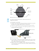
Pan Characteristics
The pan drive has a maximum pan range of ± 179° (358° total). Pan travel is capable of being
limited to a restricted range around the center of pan travel by software limits adjustable by the
programmer/end user. Pan limits refer to the horizontal range of motion available to the PosiTrack
unit. These limits are set via the Axcess program. The center position marks the center of the range.
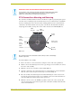
Setting the adjustable pan-limit stops
The Central Controller should be programmed by an AMX Axcess programmer before beginning.
Refer to the Specifications section on page 2 for more information on programming devices. To set
the adjustable pan-limit stops:
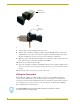
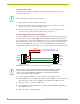
1. Ensure that there is enough slack in the lens, camera, and PosiTrack units’ AXlink cables to
accommodate the full range of pan motion.
2. Confirm that the necessary programming has been done to the system before beginning the
installation process.
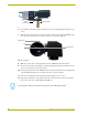
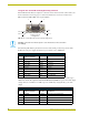
3. Mount the camera controller to the desired horizontal surface.
4. Pan the unit as far to the left as desired and enter this position into the Axcess program as the
left pan-limit stop. The LEFT limit stop MUST be set left of the Home position.
5. Pan the unit as far to the right as desired and enter this position into the Axcess program as the
right pan-limit stop. The Right limit stop MUST be set right of the Home position.
6. Pan to both programmed stop positions and ensure the pan-limit stops are set correctly.
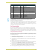
Lens Control DB-15 HD Connector Pinouts for Servomotor Mode (Cont.)
Pin
PosiTrack DB-15 HD
connector functions
Direction Lens function
6 Zoom-speed/position Output Zoom-positional/speed mode
7 Focus-speed/position Output Focus-positional/speed mode
8 Iris-local/auto Output Iris-local/auto select
9 Iris-speed/position Output Iris-positional/speed mode
10 VREF-A (+7.5V) Input VREF-A (+7.5 V). The reference voltage must be
present to operate correctly in servomotor mode.
11 VREF-B (+2.5 V) Input VREF-B (+2.5 V). The reference voltage must be
present to operate correctly in servomotor mode.
12 POT-REF+ (+5 VDC) Output POT-high side
13 POT-REF- (GND) Output POT-low side
14 Zoom-wiper (0-5 VDC) Input Zoom-POT wiper
15 Focus-wiper (0-5 VDC) Input Focus-POT wiper
Pin 1 is not required if the lens is powered independently. This feature is controlled by
the AMX/CAM switch on the connector panel. Pins 12-15 are required for Speed
mode but are not required for Positional mode.