
Instruction manual


Installation
24
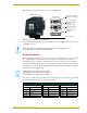
AXB-PT10/15/30 PosiTrack Camera Controllers
Using the lens control DB-15 HD (high density) connector
The PosiTrack Controllers are designed to control servomotor and motor mode camera lenses. See
the Pre-Installation section on page 7 to set the lens switches for servomotor or motor mode.
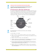
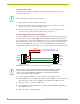
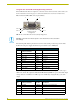
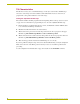
FIG. 24 shows the DB-15 HD connector pin numbers.
The following table lists the pinouts for motor mode lenses. Pin1 provides lens power from the
PosiTrack’s own power supply when the lens power switch is set to AMX (left).
Motor driven outputs are intended to drive conventional motors. These outputs can deliver up to
100 mA of current. The outputs use Pulse Width Modulation (PWM) for speed control. The output
voltage values are ± 6 VDC or ±12 VDC. Speed is controlled by varying the duty cycle of the
output.
FIG. 24 Lens control DB-15 HD connector (female) wiring pinouts
Pi
n
1Pi
n
5
Pin 6
Pin 10
Pin 11
Pin 15
Lens control DB-15 HD
(female) connector
wiring pinouts
DO NOT connect the motor-mode outputs to servo-mode lenses. This can result in
lens damage.
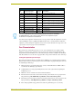
Lens Control DB-15 HD Connector Pinouts for Motor Mode
Pin
PosiTrack DB-15 HD
connector functions
Direction Lens function
1 +12 VDC Output Motor Power
2 GND Output Lens common
3 Zoom-drive Output Zoom motor
4 Focus-drive Output Focus motor
5 Iris-drive Output Iris motor
12 POT-REF+ (+5 VDC) Output POT-high side
13 POT-REF - (GND) Output POT-low side
14 Zoom-wiper Input Zoom-POT wiper
15 Focus-wiper Input Focus-POT wiper
Lens Control DB-15 HD Connector Pinouts for Servomotor Mode
Pin
PosiTrack DB-15 HD
connector functions
Direction Lens function
1 +12 VDC Output Motor Power (see following note)
2 GND Output Lens common
3 Zoom-drive Output Zoom motor
4 Focus-drive Output Focus motor
5 Iris-drive Output Iris motor