
User Guide


Programming
10
AXB-PCCOM Communications Port Interface
Response Commands
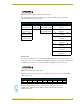
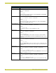
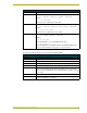
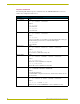
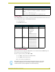
The following table lists the response commands sent to the AXB-PCCOM when set as device
number 128, configured for four devices :
Return/Requests sent to the AXB-PCCOM
Command Packet Structure and Example
Bus LED Status Syntax:
'&' <5> <STATUS> <CHECKSUM>
Examples:
"'&',5,1,44"
The bus LED is On.
"'&',5,0,43"
The bus LED is Off.
Bus Status Syntax:
'&' <6> <STATUS> <CHECKSUM>
Example
"'&',6,1,45"
The bus is on-line.When you reset AXlink, it sends BUS STATUS without being que-
ried. When AXlink goes back on-line, it sends BUS STATUS again.
"'&',6,0,44"
The bus is Off-line.
Change Level Syntax:
'&' <2> <DEVICE> <LEVEL NO> <LEVEL> <CHECKSUM>
Example:
"'&',2,1,2,132,175"
Level 2 on device 1 (AXlink device 129) is 132.
Channel Status Syntax:
'&' <1> <DEVICE> <CHANNEL> <STATUS> <CHECKSUM>
Example:
"'&',1,0,255,1,39"
Channel 255 on device 0 (AXlink device 128) is On.
"'&',1,3,100,0,142"
Channel 100 on device 3 (AXlink device 131) is Off.
Device List Syntax:
'&' <7> <# DEVICES> <DEVICES> <CHECKSUM>
Example:
"'&',7,4,128,129,130,131,55"
The AXB-PCCOM is configured for four devices, and their device numbers are 128,
129, 130, and 131.
Receive Command Syntax:
'&' <4> <DEVICE> <# BYTES> <STRING> <CHECKSUM>
Example:
"'&',4,3,9,'COMMAND 0',133"
AXCESS sent the command 'COMMAND 0' to device 3 (AXlink device 131).