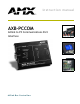
instruction manual AXB-PCCOM AXlink to PC Communications Port Interface AXlink Bus Controllers
AMX Limited Warranty and Disclaimer AMX Corporation warrants its products to be free of defects in material and workmanship under normal use for three (3) years from the date of purchase from AMX Corporation, with the following exceptions: • Electroluminescent and LCD Control Panels are warranted for three (3) years, except for the display and touch overlay components that are warranted for a period of one (1) year.
Table of Contents Table of Contents Product Information .................................................................................................1 Specifications .................................................................................................................... 2 DIP Switches ..................................................................................................................... 2 Communication Parameters.................................................................
Table of Contents ii AXB-PCCOM Communications Port Interface
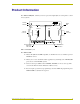
Product Information Product Information The AXB-PCCOM (FIG. 1) allows you to use a personal computer (PC) as a touch panel to control Axcess systems. TX LED AXlink LED RX LED TX RX COMMUNICATION PARAMETERS RS-232 connector HS DEVICES ON Communication Parameters DIP switch 8 7 6 5 4 3 2 1 8 7 6 5 4 3 2 1 BAUD RS-232 DEVICE CODE AXlink GND AXM AXP AXlink connector PWR ON Device Code DIP switch FIG.
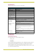
Product Information Specifications The following table details the specifications for the PCCOM. Specifications Dimensions (HWD) 1.00" x 5.26" x 3.75" (2.54 cm x 13.36 cm x 9.53 cm) Enclosure Metal with black matte finish Power Consumption 75 mA @ 12 VDC Input buffer • 12,000 bytes Output buffer (AXlink) • 12,000 bytes Baud range • 300 - 38.4 K Max. Length of SEND_STRING to device • 64 Max. Length of data packets from device • 64 Weight 8.60 oz. (243.
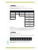
Product Information 1 2 3 4 5 6 7 8 ON FIG. 2 Communications Parameters DIP switch setting example The following table describes the Communications Parameters DIP switch settings and its corresponding DIP switch arrangements.
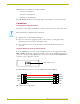
Product Information AMX standard device numbers are assigned as follows: Cards are 1 through 25. Boxes are 96 through 127. Panels are 128 through 255. The AXB-PCCOM emulates as a touch panel. Set the device number to one in the panel range. Connectors Preparing/connecting captive wires You will need a wire stripper and flat-blade screwdriver to prepare and connect the captive wires. Never pre-tin wires for compression-type connections. 1. Strip 0.25 inch of wire insulation off all wires. 2.
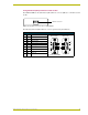
Product Information Using the RS-232 (DB-9) connector control or data The AXB-PCCOM uses the dual-function (DB-9) RS-232 connector (FIG. 6) to communicate with the PC. RS-232 connector FIG. 6 RS-232 (DB-9) connector location on AXB-PCCOM The following table lists (DB-9) RS-232 connector pinouts and signal definitions.
Product Information 6 AXB-PCCOM Communications Port Interface
Programming Programming Requests Enter the numeric value only; do not enter the brackets. Examples shown are in the Axcess programming language syntax. All values expressed in brackets are true decimal values. Replace the comma delimiter, as used in the examples, with the delimiter accepted by your PC or RS-232 device. (Refer to your PC or device user's or reference guide.) The DEVICE value is not the AXlink device code. It is the value incremented from the AXB-PCCOM DEVICE value, which should be 0.
Programming Requests sent to the AXB-PCCOM (Cont.) Command Packet Structure and Example Get Devices Syntax: '*' <9> Example: "'*',9,51" Request the devices and device numbers of the AXB-PCCOM. The AXB-PCCOM responds with a DEVICE LIST string. Get Level Status Syntax: '*' <7> Example: "'*',7,2,7,58" Request the level for level 7 on device 2 (AXlink device 130). The AXB-PCCOM responds with a CHANGE LEVEL string.
Programming Requests sent to the AXB-PCCOM (Cont.) Command Packet Structure and Example Set Level (Byte) Syntax: '*' <3> Example "'*',3,1,0,200,246" Set level 0 on device 1 (AXlink device 129) to 200. Set Level (Word) Syntax: '*' <13> Example: "'*',13,1,0,128,0,184" Set level 0 on device 1 (AXlink device 129) to 32768.
Programming Response Commands The following table lists the response commands sent to the AXB-PCCOM when set as device number 128, configured for four devices : Return/Requests sent to the AXB-PCCOM Command Packet Structure and Example Bus LED Status Syntax: '&' <5> Examples: "'&',5,1,44" The bus LED is On. "'&',5,0,43" The bus LED is Off. Bus Status Syntax: '&' <6> Example "'&',6,1,45" The bus is on-line.
Programming Return/Requests sent to the AXB-PCCOM Command Packet Structure and Example Receive String Syntax: '&' <3> <# BYTES> Example: "'&',3,0,9,'AXB-PCCOM',172" AXCESS sent the string 'AXB-PCCOM' to device 0 (AXlink device 128). Response Mask If the AXB-PCCOM receives a change, it sends data automatically. Disable this feature if the data is not used. Bits in the response mask will turn off the data. 1 = ON Data sent 0 = OFF Data not sent.
ARGENTINA • AUSTRALIA • BELGIUM • BRAZIL • CANADA • CHINA • ENGLAND • FRANCE • GERMANY • GREECE • HONG KONG • INDIA • INDONESIA • ITALY • JAPAN LEBANON • MALAYSIA • MEXICO • NETHERLANDS • NEW ZEALAND • PHILIPPINES • PORTUGAL • RUSSIA • SINGAPORE • SPAIN • SWITZERLAND • THAILAND • TURKEY • USA ATLANTA • BOSTON • CHICAGO • CLEVELAND • DALLAS • DENVER • INDIANAPOLIS • LOS ANGELES • MINNEAPOLIS • PHILADELPHIA • PHOENIX • PORTLAND • SPOKANE • TAMPA 3000 RESEARCH DRIVE, RICHARDSON, TX 75082 USA • 800.222.