instruction manual AXB-MIDI MIDI Interface AXlink Bus Controllers
AMX Limited Warranty and Disclaimer AMX Corporation warrants its products to be free of defects in material and workmanship under normal use for three (3) years from the date of purchase from AMX Corporation, with the following exceptions: • Electroluminescent and LCD Control Panels are warranted for three (3) years, except for the display and touch overlay components that are warranted for a period of one (1) year.
Table of Contents Table of Contents Product Information .................................................................................................1 Installation .................................................................................................................3 Setting the DEVICE DIP Switch ........................................................................................ 3 Preparing Captive Wires for AXlink.........................................................................
Table of Contents ii AXB-MIDI MIDI Interface
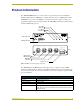
Product Information Product Information The AXB-MIDI MIDI Interface is an Axcess device for pass-through and control of Musical Instrument Digital Interface (MIDI) protocol signals. This unit can act as a MIDI matrix switcher. AXB-MIDI decodes and encodes MIDI protocol signals and routes the signals according to the programming within an Axcess Central Controller. The AXB-MIDI communicates with the Central Controller AXlink data protocols..
Product Information AXB-MIDI Specifications (Cont.) Input buffer • 3,072 bytes Output buffer (AXlink) • 6,143 bytes Max. Length of SEND_STRING to device • 64 Max. Length of data packets from device • 64 LED Indicators • AXlink Status LED (green): Lights to indicate that the AXB-MIDI is operational and interfacing with the Central Controller (when blinking once per second). • IN A LED (red): Lights to indicate that there is MIDI data present on the IN A connector.
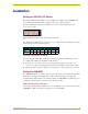
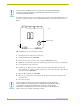
Installation Installation Setting the DEVICE DIP Switch The 8-position DIP switch (see FIG. 1) sets the AXlink device number for the AXB-MIDI. The device number must match the number assigned in the Axcess software program. The Device DIP switch example shown in FIG. 2 is set to the factory default setting of 90 (2 + 8 + 16 + 64 = 90). 1 2 3 4 5 6 7 8 FIG.
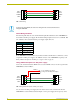
Installation PWR + PWR + AXP/TX AXP/TX AXM/RX AXM/RX GND - GND AXB-MIDI Central Controller FIG. 3 AXlink wiring If using power from AXlink, disconnect the wiring from the Central Controller before wiring the AXB-MIDI. AXlink Wiring Guidelines The following table lists wire sizes and maximum lengths allowable between the AXB-MIDI and the Central Controller power supply. The maximum wiring lengths are based on 13.5 VDC @ 100 mA available at the Central Controller's power supply output cable end.
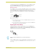
Installation accommodate the 75 mA draw of the AXB-MIDI. Make sure to connect the GND and +12 VDC wire on the AXB-MIDI AXlink connector end. Do not connect the optional +12 VDC power supply wire to the Central Controller's power supply side of the AXlink connector. MIDI cable connectors The four MIDI jacks on the rear panel (IN A, IN B, THRU and OUT) are identical 5-pin DIN type connectors. FIG. 5 shows the pinout for wiring cables to these DIN connectors.
Installation Static electricity can damage electronic circuitry. Before removing the lithium battery from the enclosure, discharge any accumulated static electricity from your body by touching a grounded metal object. You will need a flat-blade tool (non-conducting) that can be slipped under the lithium battery to pry it up and out of the socket. The location of the Lithium battery on the circuit board is shown in FIG. 7. rear Battery/socket front FIG.
Programming Programming Send Commands Send_Commands control AXB-MIDI signal routing by the Central Controller. The AXB-MIDI supports the Send_Commands described below. AXB-MIDI Send_Commands Command Description INA Syntax: Configure the destination for 'INA-' the incoming data on IN A Parameter: (see the IN A and IN B Signal = 0 to 7 Routing table on page 8). Example: SEND_COMMAND ,'INA-5' Routes incoming IN A data to THRU output and to the Central Controller.
Programming AXB-MIDI Send_Commands (Cont.) Command Description RXOFF Syntax: The AXB-MIDI will not pass on received characters to the Central Controller. This is the default. 'RXOFF' Example: SEND_COMMAND ,'RXOFF' Turns IN A and IN B transmit to the Central Controller off. TXCLR Syntax: Clear all characters waiting in 'TXCLR' both transmit buffers (MIDI Example: THRU and MIDI OUT). SEND_COMMAND ,'TXCLR' Clears THRU and OUT transmit buffers.
Programming MIDI Programming Most MIDI command strings consist of a status byte followed by one or two data bytes. The most notable exception to this is the System Exclusive which starts with a status byte of $F0, has 4 or more data bytes, then ends with a status byte of $F7. Status bytes are always $80 or greater. Status bytes are always denoted in hexadecimal. Data bytes are always less than $80 (128 in decimal). Data bytes may be denoted in either decimal or hexadecimal.
Programming SEND_STRING MIDI,"$B0 + (MIDI_CHANNEL - 1), CONTROLLER, VALUE" Specific example set volume to 50% on MIDI ch 5: MIDI_CHANNEL = 5 5 - 1 = 4 $B0 + 4 = $B4, The standard MIDI Volume controller is 7, 127 * 50% = 64 (approximately), thus the send string, SEND_STRING MIDI,"$B4, 7, 64" Selected MIDI controller numbers: BANK SELECT MSB VOLUME PAN EXPRESSION GENERAL PURPOSE GENERAL PURPOSE GENERAL PURPOSE GENERAL PURPOSE BANK SELECT LSB HOLD CONTROLLER CONTROLLER CONTROLLER CONTROLLER # # # # REVERB
Programming (* MMC STOP *) SEND_STRING MIDI,"$F0,$7F,$7F,$06,$01,$F7" (* MMC PLAY *) SEND_STRING MIDI,"$F0,$7F,$7F,$06,$02,$F7" (* MMC DEFERRED PLAY *) SEND_STRING MIDI,"$F0,$7F,$7F,$06,$03,$F7" (* MMC FAST FWD *) SEND_STRING MIDI,"$F0,$7F,$7F,$06,$04,$F7" (* MMC REW *) SEND_STRING MIDI,"$F0,$7F,$7F,$06,$05,$F7" (* MMC RECORD STROBE *) SEND_STRING MIDI,"$F0,$7F,$7F,$06,$06,$F7" (* MMC RECORD EXIT *) SEND_STRING MIDI,"$F0,$7F,$7F,$06,$07,$F7" (* MMC RECORD PAUSE *) SEND_STRING MIDI,"$F0,$7F,$7F,$06,$08,$F7"
Programming Channel Voice Messages (Cont.) Status (D7---D0) Data Bytes (D7---D0) Description 1100nnnn • 0ppppppp • Program Change. • This message sent when the patch number changes. • (ppppppp) is the new program number. 1101nnnn • 0vvvvvvv • Channel Pressure (After-touch). • This message is most often sent by pressing down on the key after it "bottoms out". This message is different from polyphonic after-touch.
Programming The following table lists and describes System Real-Time Messages: System Real-Time Messages Status (D7---D0) Data Bytes (D7---D0) 11111000 Description • Timing Clock. • Sent 24 times per quarter note when synchronization is required. 11111001 • Undefined. (Reserved). 11111010 • Start. • Start the current sequence playing. (This message will be followed with Timing Clocks). 11111011 • Continue. • Continue at the point the sequence was Stopped. 11111100 • Stop. 11111101 • Undefined.
Programming Channel Mode Messages (Cont.) Status (D7---D0) 1011nnnn (Cont.) Data Bytes (D7---D0) Description • All Notes Off. When an All Notes Off is received, all oscillators will turn Off. c = 123, v = 0: All Notes Off c = 124, v = 0: Omni Mode Off c = 125, v = 0: Omni Mode On c = 126, v = M: Mono Mode On (Poly Off) where M is the number of channels (Omni Off) or 0 (Omni On) c = 127, v = 0: Poly Mode On (Mono Off) • (Note: These four messages also cause All Notes Off).
Programming AXB-MIDI MIDI Interface 15
brussels • dallas • los angeles • mexico city • philadelphia • shanghai • singapore • tampa • toronto* • york 3000 research drive, richardson, TX 75082 USA • 469.624.8000 • 800.222.0193 • fax 469.624.7153 • technical support 800.932.6993 032-004-1335 6/02 ©2002 AMX Corporation. All rights reserved. AMX, the AMX logo, the building icon, the home icon, and the light bulb icon are all trademarks of AMX Corporation. AMX reserves the right to alter specifications without notice at any time.