
User`s guide
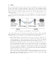
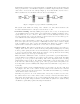


iewer’s field of view only
amera’s and viewer’s field of view
ideo wall
oom
Figure 3: Field of view of camera and viewer
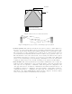
Figure 4: Diagram of proposed videoconferencing reciprocity system
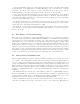
• Camera position. The camera is currently about 60 cm above the floor, with a shield above
the lens, to protect it from the light of the projected image. Unfortunately, the position of the
camera produces an image which is a little unusual, and which some people find disconcerting.
The position also prevents communication closer than about two metres from the wall. If a
person stands any closer than this, their face will not be visible to the people in the other room.
The lens shield also reduces the camera’s field of view. Ideally, the camera would be placed
approximately 1.2 metres above the floor, at eye-level for people sitting down. This would
produce a more natural image, as well as allowing communication closer to the wall, without
reducing the camera’s field of view. Overall, it will improve the system’s user-friendliness.
• Data transfer. The current system allows for audiovisual communication, but not data com-
munication. Data communication could occur through ethernet connections, but this would
allow only notebook computers to communicate, and would require some configuration. An-
other approach would be to use infra-red communication, since this would allow most notebook
and handheld computers to communicate. An added advantage of using infra-red is that no
configuration is involved — configuration is required only once; afterwards, it can be used
immediately. Also, many CSSE staff have infra-red-capable computers. It therefore makes
sense to incorporate infra-red communication into the system.
9