School of Computer Science and Software Engineering Monash University Bachelor of Computer Science (Honours) (1608) Project Report 2000 Developing support systems for an interactive video wall by Russell Clarke 12278769 rwc@cs.monash.edu.au Supervisor: Prof. David Abramson davida@csse.monash.edu.
Declaration of Originality I, Russell Clarke, declare that this thesis is my own work and has not been submitted in any form for another degree or diploma at any university or other institute of tertiary education. Information derived from the published and unpublished work of others has been acknowledged in the text and a list of references is given in the bibliography.
Abstract Videoconferencing is being increasingly used for informal communication. An example of this is Monash University’s School of Computer Science and Software Engineering. They operate a high-quality video ATM link between the staff common rooms in its Clayton and Caulfield campuses, to encourage communication and discussion between the two groups. The system consists of two FVC VANs, each with hardware MPEG-2 codecs, data projectors and cameras. Response to the videoconferencing system has been mixed.
List of Figures 1 CSSE video wall . . . . . . . . . . . . . . . . . . . . . . . . . . . . . . . . . . . . . . 1 2 Diagram of current CSSE videoconferencing system . . . . . . . . . . . . . . . . . . . 8 3 Field of view of camera and viewer . . . . . . . . . . . . . . . . . . . . . . . . . . . . 9 4 Diagram of proposed videoconferencing reciprocity system . . . . . . . . . . . . . . . 9 5 Diagram of proposed infra-red tunnelling system . . . . . . . . . . . . . . . . . . . .
Contents 1 Introduction 1 2 Background Information 2.1 Uses for Videoconferencing . . . . . . . . . . 2.2 Human Factors in Videoconferencing Systems 2.3 Features of Videoconferencing Systems . . . . 2.4 Problems with Current Systems . . . . . . . . 2.5 The Future of Videoconferencing . . . . . . . 2.6 Infra-red Data Communication . . . . . . . . . . . . . . . . . . . . . . . . . . . . . . . . . . . . . . . . . . . . . . . . . . . . . . . . . . . . . . . . . . . . . . . . . . . . . . . . . . .
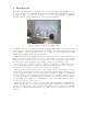
1 Introduction At Monash University’s School of Computer Science and Software Engineering (CSSE), videoconferencing systems have been installed at the staff rooms in its Clayton and Caulfield campuses (see Figure 1). The “video wall”, as it is known, is used for inter-campus seminars, departmental meetings, discussion between staff members, as well as informal chatting. Figure 1: CSSE video wall (from Abramson 2000) Response to the videoconferencing system has been mixed.
2 2.1 Background Information Uses for Videoconferencing Videoconferencing allows users who are remote from each other to work and play cooperatively. The foundations of videoconferencing are in video telephony. The first video telephone call was made in 1927 (Kraut 1994), but since then, no video telephone product has been successful. Recent developments have had more success but the telephone is still the main form of remote communication.
2.2 Human Factors in Videoconferencing Systems In 1990, Fish et al. created the VideoWindow system (Fish 1990). This used a wide-screen projector and multiple cameras and microphones to transmit the video and audio between two locations. Fish’s team used two common rooms on two floors of a building. He studied the use of the VideoWindow system for three months, recording the transactions through the system.
They analysed several live debate/interview television programmes, and came up with a system that automatically changed the camera view depending on a simple transition table. A limited amount of feedback has been obtained so far, but users seem more comfortable with the system than with a static camera angle.
picture quality, and typically use a dedicated link so bandwidth isn’t shared with LANs and Internet connections. The VideoWindow system (Fish 1990) used a specially-developed camera that captured video images which were twice as wide as a standard NTSC video image (i.e. 720 × 2 or 1440 pixels). The resulting aspect ratio is 8:3, compared to the standard 4:3. Movie film and high-definition television use an aspect ratio of approximately 16:9.
Users generally think of using videoconferencing systems as a telephone call, rather than actually meeting them face to face (Fish 1993, Cool 1992). This may be due to the main areas of research conducted so far. Most of the studies are of videoconferencing among groups of people who are working in similar (or the same) environments, but have rarely, if ever, met in reality. Videoconferencing offers many advantages over other forms of telecommunication.
there is the equivalent of only one wire (the infra-red path through the air), which has the following implications: IrDA protocols send packets one way at a time. If a device tried to send data and listen for data at the same time, it would “hear” itself and not the device it wants to communicate with. The way IrDA devices achieve two way communications is to take turns, also known as “turning the link around”. This happens at least every 500 milliseconds, and can be made more frequent as necessary.
3 Aims The video wall is currently on 24 hours a day, so that people can walk up to the wall, see if anyone is in the room and start a conversation with anyone on the other side of the wall. This is arguably its best feature in terms of usability. It is almost a standard setup, the only modification being an infra-red motion detector that turns off the projector if no movement has occurred in the room for a number of minutes, and turns it on again as soon as motion is detected.
ideo wall oom iewer’s field of view only amera’s and viewer’s field of view Figure 3: Field of view of camera and viewer Figure 4: Diagram of proposed videoconferencing reciprocity system • Camera position. The camera is currently about 60 cm above the floor, with a shield above the lens, to protect it from the light of the projected image. Unfortunately, the position of the camera produces an image which is a little unusual, and which some people find disconcerting.
Adding infra-red transceivers together with software to transmit the data across the wall would allow people with notebook or handheld computers to transmit computer files, memos, business cards, and so on across the video wall (see Figure 5). Note that the IR boxes here refer to infra-red transceivers, not the infra-red motion detectors as in Figure 4.
• Video recording. After the video is transmitted through the link, and displayed at the other location, it is lost. There are some circumstances, for example, meetings, where it would be useful to keep a record of the video conference. To address privacy concerns, people would need to be warned beforehand that video recording would be taking place. In addition, a visual indicator such as a flashing red dot could be displayed on the video wall to remind people that video recording is in progress.
Originally, three programs were going to be developed: program 1 would read from the serial port and send it to program 2, which would do a logical “and” on the state of the connections, and send the result on to program 3. Program 3 would run the “up link” and “down link” script files. After some investigation, we found it was possible to combine programs 1 and 3, which became the “client”. Program 2 became the “server”. The server would wait until two clients connected to it.
Figure 6: VidServer source files 4.3 Videoconferencing Reciprocity Application The server application, VidServer, waits for incoming calls on a pre-specified port (2000 by default). At most, two incoming calls are accepted. This type of application is also known as a daemon — it waits for connections and then handles them accordingly. The client application, VidClient, connects to the server application at a IP address specified by the user.
Figure 7: VidClient source files except for acknowledgement messages, which require the first command byte to contain 00, and the following command bytes to contain the commands received. The message received is also passed on to the projector, which can be connected on a separate COM port. This is necessary since the infra-red motion detector is now connected to the computer, rather than the projector, as was previously the case.
This function handles connection requests, and decides whether to accept a connection or not. The algorithm used here is straightforward. Two pointers are previously assigned to nil, but are assigned to stream sockets if a connection already exists. If either of the two pointers is nil, then the connection is accepted, and assigned to the (previously nil) pointer. If both are assigned non-nil values, then the connection is refused. The values of these two pointers are kept up to date.
Figure 8: VidServer main window Figure 9: VidClient configuration window sending data, disconnection from the server, whether the link is starting up or shutting down, and any errors that occur. For ease of testing, a test mode has been implemented (this can be turned on by recompiling the VidClient application with TEST defined). Figure 11 shows two VidClient applications with the test mode on.
Figure 10: VidClient main window 4.4 Infra-red Tunnelling Application The Visual C++ frameworks for the VidClient and VidServer applications were duplicated and used as a basis for the infra-red tunnelling client and server. They were renamed IRClient and IRServer. The duplicated frameworks were modified so that IRClient reads data from the serial port, buffers it, and sends it to IRServer. IRServer in turn sends it to the other client. The infra-red tunnelling application could be used for other purposes.
Figure 11: Two VidClient windows errors that occur. Individual data buffers are not shown in the event list, as they are in VidClient, since these are very frequent and are of little use to the user. IRServer, like VidServer, opens up a port on which to accept connections. It displays a window containing a list of timestamped events (see Figure 13). Events displayed mainly involve client connection and disconnection and any errors that occur. As with IRClient, data buffers are not displayed in the event list.
Figure 12: IRClient main window devices are not pointing directly at each other, or if the connection is temporarily broken by someone walking in between the two devices. As also mentioned in Section 2.6, IrDA will also vary its baud rate to maintain a “good” connection (low error rate). Bright light, for example, can introduce errors. In any case, most files sent through infra-red are small text files — business cards, memos, etc — perhaps 4K at the most.
Figure 13: IRServer main window 4.6 Automatic Switching The automatic switching application has been partially implemented, as part of the videoconferencing reciprocity application. If, in the future, three video walls exist (for example, one at the Caulfield staff room, one at the Clayton stall room, and new one at the Clayton meeting room), then there will be three VidClients trying to connect to the VidServer.
4.7 Camera Control Originally, the camera had been mounted on the wall, but since the camera repositioning, it is now set, recessed, in the wall. Some modification would be required to add the possibility of camera control, which is yet to be implemented. There are three ways to control a camera: pan, tilt and zoom. Panning refers to swivelling the camera about its x-axis (left-right), tilting refers to swivelling the camera about its y-axis (up-down) and zooming refers to magnification.
5 5.1 Discussion Videoconferencing Reciprocity Application The videoconferencing reciprocity applications were the first part of the system to be developed. As mentioned in Section 4.1, the software was developed in Visual Studio only after it was discovered that Cygnus did not support serial port communications. Having no previous experience developing under Visual Studio, much of the first few months of development was spent learning how to use Visual Studio, MFC, the Winsock API and Windows resources.
5.2 Infra-red Tunnelling Application Development of the infra-red tunnelling applications has been difficult for a number of reasons. The infra-red transceiver used, the Actisys 200L, has limited documentation, and was initially unable to be used under Windows NT. The Actisys transceiver came with driver software for Windows 95.
Figure 14: Infrared Monitor control panel showing a connection to a device of a PalmPilot (this is “Tempura” in Figure 14), and “Extended Systems Infrared” is displayed where the PalmPilot model would be shown. The QuickBeam NT software was also successfully used to transmit files from a PalmPilot. This proved that the combination of QuickBeam NT and the Actisys transceivers could be used. However, when a terminal program such as HyperTerminal was tried, no data could be received from the virtual port.
Figure 15: Infrared Monitor control panel showing no devices in range However, IRServer and IRClient have been tested successfully with null modem connections and some other serial devices. In fact, it works with any serial device that initiates its own protocol (and can withstand some latency). A MIDI keyboard is such a device, and can be used with IRServer and IRClient, although this hasn’t been tested with two MIDI keyboards.
5.4 Response Since the partial upgrading of the videoconferencing system, more use has been made of it. Recently, the weekly computer science seminars have been displayed to the other campus via the video wall. A number of meetings have also taken place over the video wall. The response to the videoconferenced seminars has generally been good. At least one minor problem has been identified when videoconferencing the seminars.
6 6.1 Conclusions Review This project has discussed the benefits of integrating new features to the existing videoconferencing system, and its aims, namely, to improve the usability and usefulness of the system. The idea has been to add new features “behind-the-scenes”, so that the new features do not cause any disruption to the current system and do not require manual human intervention. So far, the videoconferencing reciprocity server and client applications have been developed.
VidServer and VidClient could be used as the basis for a central hub for controlling video wall links. VidServer and VidClient could include a menu item and/or a button to force close a connection or reinitiate a connection, which would be useful if there were connection problems. VidServer could poll its connections to ensure that the connection was still up, and automatically disconnect any clients that did not respond within a certain time.
7 7.1 Appendices Appendix A. Source Files The complete source files for this project are available at: http://www.csse.monash.edu.au/~rwc/honsproject.zip 7.2 Appendix B. VidServer User’s Guide Before launching VidServer, you may need to configure the "server.prf" file. The format of the "server.prf" file is as follows (default value in brackets): line 1: TCP/IP port number to wait for VidClient connections on (2000) The file must be called "server.prf" and located in the same directory as VidServer.
7.3 Appendix C. VidClient User’s Guide Before launching VidClient, you may need to configure the "client.prf" file. The format of the "client.
7.4 Appendix D. IRServer User’s Guide Before launching IRServer, you may need to configure the "server.prf" file. The format of the "server.prf" file is as follows (default value in brackets): line 1: TCP/IP port number to wait for IRClient connections on (2200) The file must be called "server.prf" and located in the same directory as IRServer. After launching IRServer, you will be presented with a window containing a list. line in the list represents a different event. the list.
7.5 Appendix E. IRClient User’s Guide Before launching IRClient, you may need to configure the "client.prf" file. The format of the "client.prf" file is as follows (default value in brackets): line 1: COM port name for communication with infra-red transceiver (COM1) line 2: COM port baud rate for infra-red transceiver (9600) line 3: TCP/IP port number to connect to IRServer on (2200) The file must be called "client.prf" and located in the same directory as IRClient.
8 References (Abramson 2000) http://www.csse.monash.edu.au/~davida/VirtualTeaRoom/ (Actisys 2000) http://www.actisys.com/ (Brookings 1999) Brookings Institution, “Cyber scholars build virtual bridges”, Communications News, February 1999, vol. 36, issue 2, p. 80. (Cool 1992) Cool, C., Fish, R. S., Kraut, R. E. and Lowery, C. M., “Iterative design of video communication systems”, Conference Proceedings on Computer-supported Cooperative Work, November 1–4, 1992, Toronto Canada, pp. 25–32.
(Kraut 1994) Kraut, Robert E., Rice, Ronald E., Cool, Coleen and Fish, Robert E., “Life and Death of New Technology: Task, Utility and Social Influences on the Use of a Communication Medium”, Proceedings of the Conference on Computer-supported Cooperative Work, October 1994, Chapel Hill, NC, USA pp. 13–21. (Panja 2000) http://www.panja.com/ (Perey 2000) Perey, Christine, “But implementation is still fuzzy; Topology, bandwidth and QoS questions remain open”, Network World, March 13, 2000, p. 54.
9 Glossary of Terms Actisys Company who manufactures infra-red transceivers. ATM Asynchronous Transfer Mode, a low-latency, fast computer network. CSSE Monash University School of Computer Science and Software Engineering. Extended Systems Company who produces QuickBeam. First Virtual Company who manufactures the VAN. FVC First Virtual Corporation. IR Infra-red. IrDA Infra-red Data Association.