
User Guide


Product Information
4
AXB-EM232 Enhanced Master RS-232 Controller
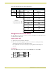
Refer to the following table when setting the DIP switches.
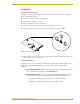
Wiring Devices to the AXB-EM232
The AXB-EM232 has captive-wire connectors on the rear panel (FIG. 1) for AXlink, RS-232, RS-
232, RS-422, and 12 VDC power.
Preparing captive wires
1. Strip 0.25 inch of wire insulation off all wires.
2. Insert each wire into the appropriate opening on the connector according to the wiring
diagrams and connector types described in this section.
Do not tighten the screws excessively; doing so may strip the threads and damage the
connector.
Using AXlink
Connect the AXlink wiring to the connector on the AXB-EM232, as shown in FIG. 3.
Communication Parameters DIP Switch Settings
Switch1 2 3456 7 8
Function Stop Bits Data Bits Parity Baud Rates
Setting Off Off Off Off Off Off Off Off
Value 2 bits 7 bits Unused 300
On On On Off Off On Off Off
1 bit 8 bits Unused 600
Off On Off Off On Off
Unused 1,200
On On Off On On Off
Unused 2,400
Off Off On Off Off On
Mark 4,800
On Off On On Off On
Even 9,600
Off On On Off On On
Odd 19,200
On On On On On On
None 38,400
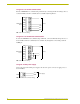
FIG. 3 AXlink wiring
PWR
AXP
AXM
GND
PWR
AXP
AXM
GND
AXlink Device